
PIC16F628 Timer Interrupt Programming Tutorial
by Lewis Loflin
The complete assembly file for this demo is at TRM0_IRQ.asm
The Microchip PIC series of micro-controllers have a number of programmable interrupt sources. In this tutorial we will use 8-bit timer 0 (TMR0) to generates an interrupt every ~16.4 mSec. which increments variable CNT (0x23) which at 61 counts toggle an LED ON-OFF on RA0.
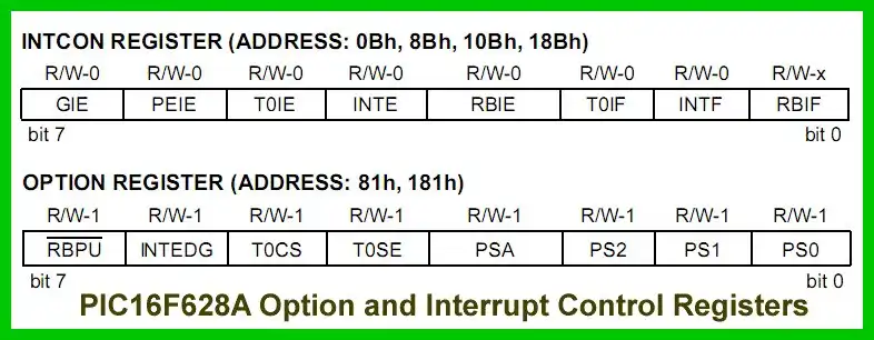
The 8-bit option register (81H BANK1) controls TMR0 while interrupt control register (0x0B BANK0) as follows in setup section by clearing and setting bits in the appropriate registers. See above for labels.
	; setp TMR0 interrupts
	banksel OPTION_REG ; Reg. 0x81 BANK1
	movlw b'10000111'
	; internal clock, pos edge, prescale 256
	movwf OPTION_REG
	banksel INTCON ; Back 0x0B BANK1
	bsf INTCON, GIE ; enable global interrupt
	bsf INTCON, PEIE ; enable all unmasked interrupts
	bsf INTCON, T0IE ; enable TMR0 interrupt
	bcf INTCON, T0IF ; clr TMR0 interrupt flag
	; to turn on, must be cleared after interrupt
	clrf	CNT ; RAM location 0x23
Using a 16 mHz crystal this is divided by 4 then divided by 256 will increment TMR0 every 64 uSec. and after 255 increments times out to 16.32 mSec. will generate an interrupt.
;***************************
	ORG     0x000
	; processor reset vector
	goto    setup
	; go to beginning of program

	ORG     0x004
	; interrupt vector location
; isr code can go here or be located
; as a call subroutine elsewhere

	movwf   w_temp
	; save off current W register contents
	movf	STATUS,w
	; move status register into W register
	movwf	status_temp
	; save off contents of STATUS register
	movlw d'61'
	; approx 61 interrupts =
	; 1 sec. at 16 mHz crystal
	subwf CNT, w
	btfss STATUS, Z ; i = 10
	goto $+4
	call toggle
	; state = !state PORTA, 0
	clrf CNT
	goto $+2
  	incf CNT
	bcf INTCON, T0IF
	; clr TMR0 interrupt flag

	movf    status_temp,w
	; retrieve copy of STATUS register
	movwf	STATUS
	; restore pre-isr STATUS register contents
	swapf   w_temp,f
	swapf   w_temp,w
	; restore pre-isr W register contents
	retfie
	; return from interrupt

;***********************************
Referring to above the interrupt vector is at location 0x04 while the reset vector is at 0x00. The code below "ORG 0x004
Every interrupt generated by TMR0 vectors to ORG 0x04 executing code below it - will tehn save W and STATUS registers. Initialized to 0 variable CNT is incremented on each pass, then by subtracting 61 and checking the Z flag in the STATUS register when equal will set the flag, clear.
If not equal CNT is incremented, TMR0 IRQ flag is cleared, W and STATUS registers are retrieved. Then a return from interrupt (retfie) returns to the main program. The process is repeated.
If during the pass CNT = 61 the Z flag is set, the state on the LED on RA0 is toggled, CNT is set to 0, TMR0 IRQ flag is cleared, W and STATUS registers are retrieved. Then a return from interrupt (retfie) returns to the main program.
See How I got into Electronics

- You Tube Videos for this Series
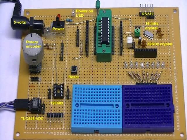
- Home Built PIC Development Board
- PIC16F628 PIC Using Rotary Encoder to Operate Stepper Motor
- Using a Serial ADC with PIC16F628
- Calculating Pulse-Width Modulation with a PIC
- PIC16F84A-628A Hardware Time Delays
- PIC16F84A-628A Timer Interrupt Delays
- PIC16F84A-628A Pullups and Interrupts
- PIC16F84A-628A Hardware Interrupts Tutorial
- Projects using PIC16F628:
- Home Built PIC16F628 Prototyping Board
- Exploring the Microchip PIC in Assembly
- Using a Microchip PIC with TLC548 Serial ADC
- Controlling PIC Pulse Width Modulation with a Serial ADC
- Using TMR0 on a PIC with Interrupts
- External Clock Crystal with PIC16F628 TMR1 Generates Interrupt
- PIC Using Rotary Encoder to Operate Stepper Motor
- PIC16F628 Pulse Width Modulation Controls Brightness of LED
- Another way to Turn On-Off PWM in a PIC
- TLC548 Serial ADC Spec. Sheet
- Programming PIC16F84A-PIC16F628A Interrupts by Example
- PIC16F84A-PIC16F628A Pull Up Resistors with Interrupts
- Programming PIC16F84A-PIC16f628a Timers by Example
- Programming PIC16F84A-PIC16F628A TMR0 Interrupts
- Programming PIC16F84A Software Delay Routines by Example
Web site Copyright Lewis Loflin, All rights reserved.
If using this material on another site, please provide a link back to my site.