External Crystal Uses PIC16F628 TMR1 Generates Interrupt
by Lewis Loflin
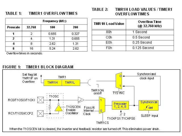
A crystal oscillator circuit is built in between pins T1OSI (input) and T1OSO (amplifier output). It is enabled by setting control bit T1OSCEN (T1CON bit 3). The oscillator is a low power oscillator rated up to 200 kHz. It will continue to run during SLEEP. It is primarily intended for a 32 kHz crystal.
As a 16-bit timer with it's own clock source a real time clock base is easy to implement. Note the values in Tables 1 and 2 above. Compare to using TMR0 at PIC16F628 Timer 0 Interrupt Programming Tutorial.
The full ASM can be downloaded: PIC16F628A_TMR1.asm
;*****************************

	ORG     0x000
	; processor reset vector
	goto    setup
	; go to beginning of program


	ORG     0x004
	; interrupt vector location begin here
	movwf   w_temp
	; save off current W register contents
	movf	STATUS,w
	; move status register into W register
	movwf	status_temp
	; save off contents of STATUS register

; ISR code can go here or be located
; as a call subroutine elsewhere

	movlw 0x80 ; reload TMR1
	movwf TMR1H
	bcf PIR1, TMR1IF ; clr TMR1 interrupt flag
	call toggle ; flip state on RA0

; end ISR
	movf    status_temp,w
	; retrieve copy of STATUS register
	movwf	STATUS
	; restore pre-isr STATUS register contents
	swapf   w_temp,f
	swapf   w_temp,w
	; restore pre-isr W register contents
	retfie
	; return from interrupt

;*******************************************
Above is the interrupt service routine or ISR. Again we save the W and STATUS registers and restore before RETFIE ending the ISR.
	bsf	PIE1, TMR1IE ; enable TMR1 interrupt
	banksel INTCON
	clrf PORTA
	clrf PORTB
	bsf INTCON, GIE
	; enable global interrupt
	bsf INTCON, PEIE
	; enable all unmasked interrupts

	bcf PIR1, TMR1IF
	; clr TMR1 interrupt flag
	clrf T1CON
	bsf T1CON, TMR1ON
	; Timer1 On bit
	bsf T1CON, TMR1CS
	; external oscillator crystal
	bsf T1CON, 2
	; T1SYNC set to asynchronous
	bsf T1CON, T1OSCEN
	; Timer1 Oscillator Enable Control bit
	; two lines below same as 5 lines above
	; movlw b'00001111'
	; movwf T1CON

	clrf TMR1L
	; set to 0
	movlw 0x80
	; value for 1 sec. delay
	movwf TMR1H
	; must be reloaded after every interrupt
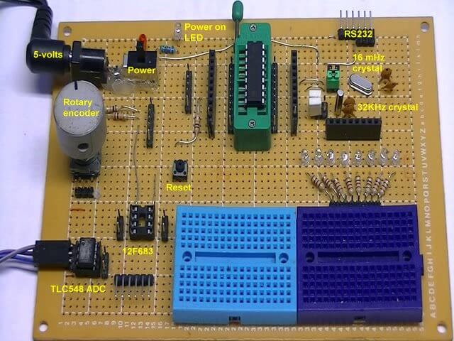
Above is the setup code to use the 32 kHz. crystal programmed to generate an interrupt every 1 second. This is regardless of the frequency of the main system clock in my case a 16 mHz. crystal.
See How I got into Electronics

- You Tube Videos for this Series
- Home Built PIC Development Board
- PIC16F628 PIC Using Rotary Encoder to Operate Stepper Motor
- Using a Serial ADC with PIC16F628
- Calculating Pulse-Width Modulation with a PIC
- PIC16F84A-628A Hardware Time Delays
- PIC16F84A-628A Timer Interrupt Delays
- PIC16F84A-628A Pullups and Interrupts
- PIC16F84A-628A Hardware Interrupts Tutorial
- Projects using PIC16F628:
- Home Built PIC16F628 Prototyping Board
- Exploring the Microchip PIC in Assembly
- Using a Microchip PIC with TLC548 Serial ADC
- Controlling PIC Pulse Width Modulation with a Serial ADC
- Using TMR0 on a PIC with Interrupts
- External Clock Crystal with PIC16F628 TMR1 Generates Interrupt
- PIC Using Rotary Encoder to Operate Stepper Motor
- PIC16F628 Pulse Width Modulation Controls Brightness of LED
- Another way to Turn On-Off PWM in a PIC
- TLC548 Serial ADC Spec. Sheet
- Programming PIC16F84A-PIC16F628A Interrupts by Example
- PIC16F84A-PIC16F628A Pull Up Resistors with Interrupts
- Programming PIC16F84A-PIC16f628a Timers by Example
- Programming PIC16F84A-PIC16F628A TMR0 Interrupts
- Programming PIC16F84A Software Delay Routines by Example
Web site Copyright Lewis Loflin, All rights reserved.
If using this material on another site, please provide a link back to my site.