
Fig. 1 Click for larger image.
Introduction TC4420-TC4429 MOSFET Drivers
Right-click on image open in new tab for full size image.
Here I will introduce the TC4420/TC4429 MOSFET drivers. They solve a number of technical problems driving low-voltage motor drive circuits using MOSFETs.
The TC4420 is non-inverting while the TC4429 is inverting. Otherwise there are no differences in the devices. See Fig. 1 above.
In other pages I'll address the use of TC4420/TC4429 in H-Bridge circuits and even driving bipolar transistors.
The voltages are limited to 20V due to the 20V Vgs of most MOSFETs including those internal to the TC4420/TC4429s.
MOSFETs are popular among hobbyists and engineers using various microcontrollers such as the Arduino, Microchip PIC, and PICAXE. Along with the popular Raspberry PI their outputs are 3.3-volts or 5-volts.
The problem becomes is many MOSFETs won't turn on at all at 3.3-volts and many not fully on at even 5-volts. Ditto IGBTs that my tests show require at least 7-volts or more.
This becomes a real problem with high-power and high-current circuits. Without full turn-on we get excessive heating of the MOSFET, voltage drop across the MOSFET, and wasted power. Heating up the MOSFET does not deliver power to the load.
See my YouTube video Why Your MOSFET Transistors Get Hot.
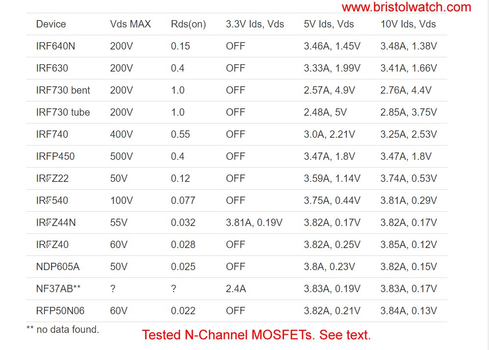
Fig. 2 Click for larger image.
Fig. 2 illustrates the test result of a number of N-channel MOSFETs. Issues became clear during the tests one must make note of.
Higher voltage MOSFETs such as the IRF740 have a high Rds(on) resistance. This can lead to excessive voltage drop with low-voltage, high current loads. Dropping 2-3-volts at 180-volts is no problem. At 12 or 6 volt loads this is a big problem.
For low-voltage loads use lower voltage MOSFETs such IRFZ44N that works great even at 3.3-volts.
See Test Power MOSFET Transistors, IGBTs Results, Observations.
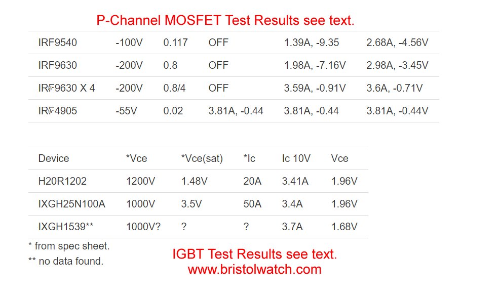
Fig. 3 Click for larger image.
Fig. 2 illustrates the same problem with P-channel MOSFETs. P-channel MOSFETs are less common and harder to find thus more expensive. I would use the IRF4905 for low-voltage loads. They connect directly to 3.3-volts connections.
I also included insulated-gate-bipolar-transistors (IGBTs) which are simply not suited at all for low-voltage loads. They also require a higher drive voltage.
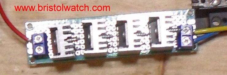
Fig. 4 Click for larger image.
Remember: MOSFETs and IGBTs are voltage operated devices; bipolar transistors are current operated devices! MOSFETs and IGBTs do introduce gate-source capacitance which when the devices are connected in parallel can cause other problems.
Fig. 4 illustrates 4 IRF9630s connected in parallel to reduce the high Rds(on) problem. But my test clearly show the gate-source capacitances added together. While still a voltage operated device gate-source capacitance charge/discharge can be a problem in both the driver circuits and with frequency response.
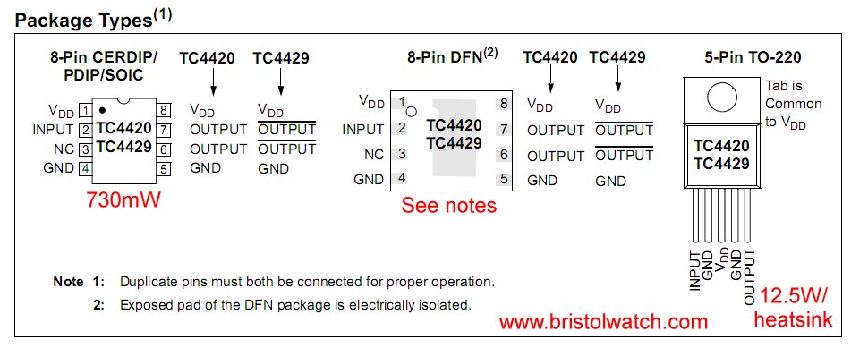
Fig. 5 Click for larger image.
Where to buy these parts? The TC4420CAT the high power TO-220 is available from Mouser or Digikey for $2.95 Qty 1.
A direct substitute is the MCP1406 (non-inverting) and MCP1407 (inverting) for $1.74 Qty 1.
I bought 5 of the TC4420CPA DIP8 off of Ebay for $4.36 with shipping from Taiwan.
Why use a TC4420/TC4429?
From the manufacture's specification sheet:
The TC4420/TC4429 are 6A (peak), single-output MOSFET drivers. The TC4429 is an inverting driver while the TC4420 is a non-inverting driver. These drivers are fabricated in CMOS for lower power and more efficient operation versus bipolar drivers.
Both devices have TTL/CMOS compatible inputs that can be driven as high as VDD + 0.3V or as low as –5V without upset or damage to the device. This eliminates the need for external level-shifting circuitry.
The output swing is rail-to-rail, ensuring better drive voltage margin, especially during power-up/power-down sequencing. Propagational delay time is only 55ns (typical) and the output rise and fall times are only 25ns (typical) into 2500pF across the usable power supply range.
Fig. 1 illustrates the internal equivalent circuit for a TC4420/TC4429. The input circuits have a broad range from -5V to VDD. That means anything from 3.3V to 15-volt CMOS or 5V TTL logic will work as is.
The output MOSFETs can source/sink 6 amps peak and have a low output impedance. That mean fast rise-fall times. When they say "rail-to-rail" that mean nearly VDD to ground.
Fig.5 illustrates the various available packages. I used the 8-pin dip package rated at 730mW. The spec sheet was unclear about constant current use versus peak current. I would limit the DIP8 current to 1 amp.
Note: the spec sheet warns that on packages with dual outputs both must be connected.
The TO-220 version can carry a lot of current with a heat sink. In fact these can be used directly as a half H-bridge as I'll show on another webpage.
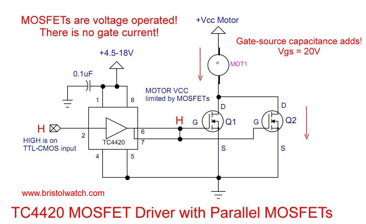
Fig. 6 Click for larger image.
Fig. 6 illustrates a TC4420 driving parallel N-channel MOSFETs. The connection is the same with a single n-channel MOSFET. A HIGH input will turn ON the MOSFET(s).
If the input pin to the TC4420 is left floating the output will be low. I'd advise tying the to ground through a 2.2k resistor.
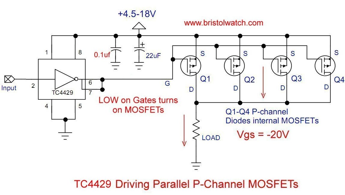
Fig. 7 Click for larger image.
Fig. 7 illustrates the TC4429 driving parallel P-channel MOSFETs such as those in Fig. 4.
This can be tricky because a LOW input will turn on the MOSFETs. If the input pin is left floating tie it to digital Vcc through a 4.7K resistor.
That completes this introduction. The following projects will include operating an H-bridge and several alternate uses.
- Quick navigation of this website:
- Basic Electronics Learning and Projects
- Basic Solid State Component Projects
- Arduino Microcontroller Projects
- Raspberry Pi Electronics, Programming
- Introduction TC4420-TC4429 MOSFET Drivers
- Use TC4420 MOSFET Driver for Simple H-Bridge Circuit
- TC4420 MOSFET Driver Various Circuits
- TC4420 MOSFET Driver Replacement Circuits
- YouTube Videos
- Introduction TC4420-TC4429 MOSFET Drivers
- Circuit Examples for TC4420-TC4429 MOSFET Drivers
- TC4420 H-Bridge Circuit
- TC4420 MOSFET Driver Replacement Circuits
- TB6600 Stepper Motor Driver with Arduino
- Interfacing Microcontrollers to CMOS and MOSFET Circuits
- Simplified CMOS-MOSFET H-Bridge Circuit
- Tri-State H-Bridge using CD4093B CMOS Circuit
- Common Collector Opto-Isolated Bipolar Transistor Switches
- Compare 2N3055 MJE10005 Transistor Power Switches
- Compare 2N3055 MJE10005 Transistor Power Switches
- Optical Isolation of H-Bridge Motor Controls
- All NPN Transistor H-Bridge Motor Control
- Transistor Driver Circuits
- ULN2003A Darlington Transistor Array with Circuit Examples
- Tutorial Using TIP120 and TIP125 Power Darlington Transistors
- Driving 2N3055-MJ2955 Power Transistors
- Understanding Bipolar Transistor Switches
- N-Channel Power MOSFET Switching Tutorial
- P-Channel Power MOSFET Switch Tutorial
- Build a Transistor H-Bridge Motor Control
- H-Bridge Motor Control with Power MOSFETs
- More Power MOSFET H-Bridge Circuit Examples
- Build a High Power Transistor H-Bridge Motor Control
- H-Bridge Motor Control with Power MOSFETs Updated
- Opto-Isolated Transistor Drivers for Micro-Controllers
Web site Copyright Lewis Loflin, All rights reserved.
If using this material on another site, please provide a link back to my site.