
Interfacing Arduino IR Sensor Module
The Keyes Infrared IR Sensor Obstacle Avoidance Sensor board is an inexpensive solution to avoidance detection for robotics and other electronics uses. Costing under $5 with shipping operation is simple and straightforward.
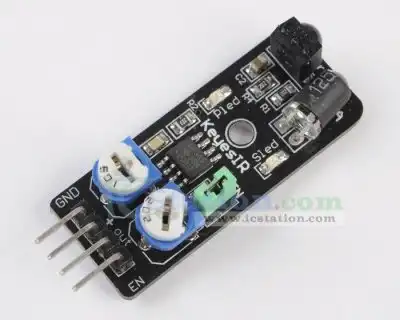
This comes as an assembled module as shown above there are only four pins: +5-volts, GND, output, and EN. Output is an active LOW and has a onboard status LED. It's very easy to interface directly with Arduino, Picaxe, or Microchip PIC micro-controllers.
It also works with the Raspberry Pi with a voltage range of 3-6 volts. Connect Vcc to 3-volts!
The enable pin "EN" will disable the device when HI (Vcc) and enable when LO (GND). The onboard jumper can be left open to allow external control of enable/disable of the module. I see no use for this function and would leave the jumper on and the pin disconnected.
There are two potentiometers on the module one controlling operating frequency (centered at 38 kHz) the other controlling intensity. The detector was designed for 38 kHz and the onboard oscillator circuit is based on a 555 timer. Tweaking gives a little better range but I'd suggest leaving it alone because the useful range is narrow.
It worked well as is. The maximum reliable range in my test was around 30-40 cm and depended on the type of material. A smooth white surface worked far better than a black or rough surface.
If one wants to purchase this sensor module click the above banner or this link. They also have a number of other useful items for the hobby robotics and electronics builder. They are offering a 10% discount through February 14, 2014. Use offer code "lewics". I'm not being paid for this.
The video above shows how this is used with an Arduino Nano.
- Microchip PIC 18F2550
- Assembly language projects using PIC16F628
- PICAXE Microcontroller Projects
- Arduino Microcontroller Projects
- General Electronics Learning and Projects
- My YouTube Videos on Electronics
#define Bit_out 12 // Pin 1-2 Sn74164 #define CLK 11 // Pin 9 Sn74164 #define RS 7 // Pin 4 LCD #define E 8 // Pin 6 LCD #define sensorPin 4 #define Line1 0x80 // location LCD row 0 col 0 or line 1 LCD #define Line2 0x80 + 0x40 // location row 1 col 0 or line 2 LCD int count = 0; void setup() { pinMode(Bit_out, OUTPUT); pinMode(CLK, OUTPUT); pinMode(RS, OUTPUT); pinMode(E, OUTPUT); pinMode(sensorPin, INPUT); digitalWrite(CLK, LOW); digitalWrite(RS, LOW); // LCD in command mode default digitalWrite(E, HIGH); initLCD(); // see below delay(500); typeln("Count = 0 ", Line2); } void loop() { // below simply prints "Hello World!" on line 1 // char String1[] = "Hello world!\n"; // typeln(String1, Line1); // change a float to ASCII // dtostrf(floatVar, X, Y, charBuf); // X is min String Width Inc Decimal Point // Y is num Vars After Decimal point // sensor low when object detected typeln("Detector Off ", Line1); if (!digitalRead(sensorPin)) { typeln("Detector On ", Line1); typeln("Count = ", Line2); count++; typeInt(count, Line2 +9); while (!digitalRead(sensorPin)) {} // wait for release } } // end loop // location is place on LCD display. void typeInt(int k, int location) { char array1[10]; itoa(k, array1, 10); // int to string typeln(array1, location); } void typeChar(byte val) { ssrWrite(val); digitalWrite(RS, HIGH); pulseOut(E); digitalWrite(RS, LOW); } void writeCommand(byte val) { ssrWrite(val); // send byte to 74164 digitalWrite(RS, LOW); // make sure RS in Com mode pulseOut(E); } // Below we pass a pointer to array1[0]. void typeln(char *s, int location) { delayMicroseconds(1000); writeCommand(location); // where to begin while (*s) typeChar(*(s++)); } // end typeln // inverts state of pin, delays, then reverts state back void pulseOut(byte x) { byte z = digitalRead(x); delayMicroseconds(10); z = !z; // reverse state digitalWrite(x, z); z = !z; // return to original state digitalWrite(x, z); } // end pulsout() /* To shift LSB out first: byte temp = val & B00000001; if (temp == 0x01) digitalWrite(Bit_out, HIGH); else digitalWrite(Bit_out, LOW); pulsout(CLK); val = val >> 1; // shift one place right */ void ssrWrite(byte val) { // shift data to 74164 for (int j=1; j<=8; j++) { // shift out MSB first byte temp = val & B10000000; // MSB out first if (temp == 0x80) digitalWrite(Bit_out, HIGH); else digitalWrite(Bit_out, LOW); pulseOut(CLK); val = val << 1; // shift one place left } // next j } // end byteWrite /* Hd44780 display commands: 0x0f = initiate display cursor on blinking 0x0c = initiate display cursor off 0x01 = clear display fills display with spaces (0x20). 0x02 = HOME returns to line one first character 0x38 = 2 lines X 16 char 8 bits mode. Defaults to 1 line mode. 0x10 = cursor left 0x14 = cursor right 0x18 = Shifts entire display left 0x1c = Shifts entire display right One can also go to a specific location. writeCommand(0x80); // begin on 1st line writeCommand(0x80 + 0x40); // begin on 2nd line writeCommand(0x38); // setup for 2 lines writeCommand(0x0F); // blinking cursor writeCommand(0x02); // home writeCommand(0x01); // clear */ void initLCD(void) { writeCommand(0x38); // setup for 2 lines writeCommand(0x0F); // blinking cursor writeCommand(0x01); // clear writeCommand(0x02); // home } void ClearDisplay(void) { writeCommand(0x01); // clear writeCommand(0x02); // home }
- In Depth Look at AC Power Control with Arduino
- YouTube Video for Arduino AC Power Control
- Four part series:
- Experimenting with the PCA9555 32-Bit GPIO Expander with Arduino
- PCA9555 32-Bit GPIO Expander with Arduino and a 4X4 Keypad
- PCA9555 32-Bit GPIO Expander with Arduino Using Interrupts
- PCA9555 32-Bit GPIO Expander with Arduino and LCD Display
- YouTube Video for Series
Added June 7, 2013:
- Rotary Encoder Used with Arduino Interrupts
- Connecting Arduino to a 74C164 Shift Register
- Using the Mc3479 Stepper Motor Controller with Arduino
- Build a Thermocouple Amplifier
- My YouTube Channel
You Tube Arduino Microcontroller Video Series March 2012:
- Introduction to Arduino
- Part 1: Programming Arduino Outputs
- Part 2: Programming Arduino Inputs
- Part 3: Programming Arduino Analog to Digital Conversion
- Part 4: Programming Arduino Pulse Width Modulation
- Arduino stepper motor control
- Quick navigation main page:
- Arduino Microcontroller Projects
- General Electronics Learning and Projects
- Raspberry Pi and Linux
- Connecting a PC Printer Port to Electronics with Python
- Microchip PIC 18F2550
- PICAXE Microcontroller
- Gen. Electronics
- My YouTube Channel
- Raspberry Pi & Linux
- Arduino Projects
- PIC18F2550 in C++
- PIC16F628A in Assembly
- PICAXE Projects
- Web Master
- Bristol VA/TN
- Environmentalism
- US Constitution
- Religious Themes 1
- Religious Themes 2