 Fig. 1
Arduino XOR Blinks LED
by Lewis Loflin
This is part of a series on code snippets for Arduino. Many visitors to my You Tube Channel and this website are beginners. They have limited knowledge of programming or hardware. This requires learning both.
Think of a micro-controller as a box full of basic logic circuits, gates, etc. To control the "box" we have to tell it what hardware to use. We must tell the "box" how to manipulate the gates and hardware. that is what machine code does.
I am using compiler Arduino-1.6.3. Results may vary with other compilers or a non-Nano Arduino board.
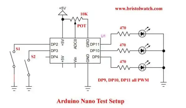
Fig. 1 shows the test setup for this series, in this case an Arduino Nano. I'll assume one can program their Arduino board. The Nano and most Arduino boards today have an LED on digital pin 13 (DP13).
Arduino uses a variation of C/C++ a complied language. That means the written code usually as a text file. This text file is "compiled" etc. to machine code that is written to the hardware. While C/C++ are much the same across most micro-controllers, the machine code is not.
The sequence is 1) write code text file (.ino for Arduino), 2) it is checked and compiled, 3) machine code uploaded to Arduino.
A few notes on this. "HIGH" can be replaced with "1"; "LOW" can be replaced with "0". So digitalWrite(LED, HIGH) is the same as digitalWrtie(LED, 1). Same with LOW and 0.
In the electrical sense a HIGH or 1 is 5-volts; a LOW or 0 is 0-volts or ground.
And "true" can be replaced by "1" or any non-zero number; "false" can be replaced by "0". I'll look at code for that as well.
- Arduino IF Statement Code Examples
- Arduino Solid State Relay Motor Enable Control
- Arduino XOR Blinks LED
- Arduino Projects Revisited Revised
- Programming ADS1115 4-Channel I2C ADC with Arduino
- Arduino uses ADS1115 with TMP37 to Measure Temperature
- Connect Arduino to I2C Liquid Crystal Display
- Arduino Reads Temperature Sensor Displays Temperature on LCD Display
- Arduino with MCP4725 12-bit Digital-to-Analog Converter Demo
- Videos
- Arduino with ADS1115 4-Channel 16-bit Analog-to-Digital Converter
- Arduino with MCP4725 12-Bit DAC
- Using Zero-Crossing Detectors with Arduino
- Hardware Interrupts Demo and Tutorial for Arduino
- In Depth Look at AC Power Control with Arduino
- Micro-controller AC Power Control Using Interrupts
- Light Activated SCR Based Optocouplers Circuit Examples
- Solid State AC Relays with Triacs
- YouTube
- Zero-Crossing Detectors Circuits and Applications
- Zero-Crossing Circuits for AC Power Control
- In Depth Look at AC Power Control with Arduino
- Micro-controller AC Power Control Using Interrupts
- YouTube Video for Arduino AC Power Control
- Arduino
- Arduino PWM to Analog Conversion
- Arduino Analog Digital Conversion Voltmeter
- Better Arduino Rotary Encoder Sensor
- Simple 3-Wire MAX6675 Thermocouple ADC Arduino Interface
- YouTube:
- 3-Wire MAX6675 Thermocouple ADC Arduino Interface
- Arduino ADC Voltmeter YouTube video
- Arduino PWM to ADC YouTube video
- Arduino Nano Test Template
- Arduino Solid State Relay Motor Enable Control
- Arduino Blink LED Tutorial
- Arduino SSR Power Enable Program
- SSR Based High Voltage H-Bridge
- Arduino H-Bridge Motor Control Program with LCD Display
- Arduino XOR Blinks LED
- Arduino Motor Control Program Using IF
- ULN2003A Darlington Transistor Array with Circuit Examples
- Tutorial Using TIP120 and TIP125 Power Darlington Transistors
- Driving 2N3055-MJ2955 Power Transistors with Darlington Transistors
- Understanding Bipolar Transistor Switches
- N-Channel Power MOSFET Switching Tutorial
- P-Channel Power MOSFET Switch Tutorial
- H-Bridge Motor Control with Power MOSFETS
- More Power MOSFET H-Bridge Circuit Examples
- Build a High Power Transistor H-Bridge Motor Control