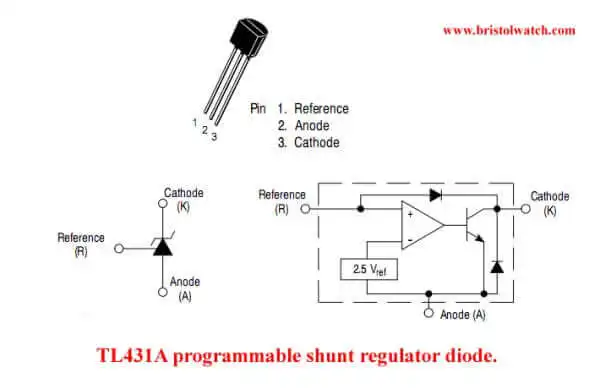
Fig. 1
Experiments with TL431A Shunt Regulator
by Lewis Loflin
In simple terms the TL431A acts a temperature compensated variable/adjustable Zener diode. It can also act as a voltage reference or constant current source..
The TL431A, B integrated circuits are three−terminal programmable shunt regulator diode. These monolithic IC voltage references operate as a low temperature coefficient Zener diode.
Related: Zener Diode Regulator Circuits.
The 2.5 V internal reference makes it convenient to obtain a stable reference for 5.0 V logic supplies. Since the TL431A, B operates as a shunt regulator, they can be used as either a positive or negative voltage references.
The TL431A is programmable from Vref to 36 V with only two external resistors. These devices exhibit a wide operating current range of 1.0mA to 100 mA with a typical dynamic impedance of 0.22 Ohms.
The characteristics of these references make them excellent replacements for Zener diodes in many applications such as digital voltmeters, power supplies, and op amp circuitry.
In addition to good temperature compensation and stability, the TL431A has the following features:
- Programmable Output Voltage to 36 V
- Voltage Reference Tolerance: +-0.4%, @ 25°C (TL431B)
- Low Dynamic Output Impedance, 0.22 Ohms Typical
- Sink Current Capability of 1.0 mA to 100 mA
Note: the values used below were experimental and may not reflect actual values in finished products. These circuits were built and tested and come with no warranty.
Tricks and Tips for the LM78XX Series Voltage Regulators
Basic Power Supply Rectification Tutorial
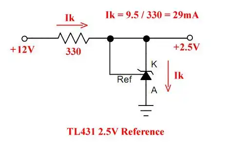
Fig. 2
In Fig. 2 we use the TL431A as a simple 2.5 volt reference. This is far more temperature stable than a Zener diode. Choose a resistor values to limit Ik to between 20mA and 40mA.
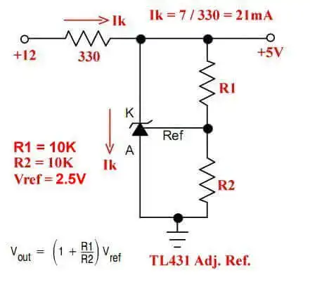
Fig. 3
In Fig. 3 we use a voltage divider to create a 5 volt reference. The output voltage equals (1 + R1 / R2) * 2.5V. Because finding the right values for R1 and R2 we can use a potentiometer.
In this case it would be 5 / 2.5 = 2; 2 - 1 = 1. Two equal resistors for R1 and R2 would work: 10K for each.
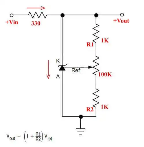
Fig. 4
Fig. 4 uses a 100K potentiometer to create a variable voltage reference. for 5 volts the 100K potentiometer would be set dead center. This makes it easy to create a stable variable sort of Zener diode.
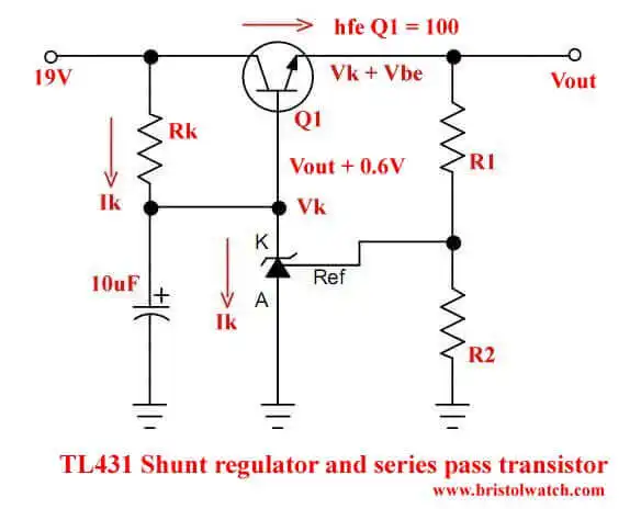
Fig. 5
In Fig.5 we use a series pass transistor to boost current. Calculate Rk to limit Ik to no more than 10-40 mA. The voltage on the base of the transistor must be calculated at VOUT + 0.6V to make up for the EB voltage drop.
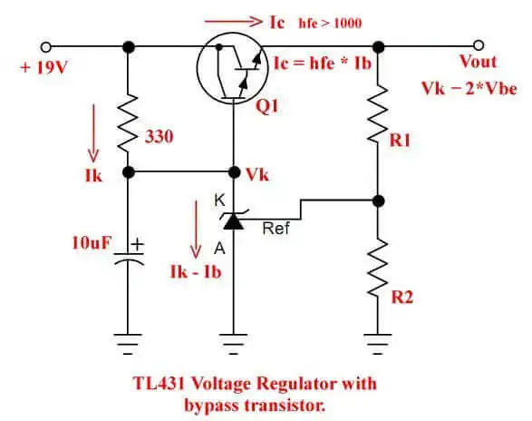
Fig. 6
Fig. 6 works exactly like Fig. 5 except for using a Darlington pass transistor. The transistor based voltage must be VOUT + 1.2 volts.
This produces a higher current output.
- Experiments with TL431 Shunt Regulator
- TL431A Precision Current Regulator Circuits
- TL431A Based Current Limiter Constant Current Source Circuits
- TL431A Shunt Regulator Circuits
- Using TL431A Li-Ion Battery Charger Tutorials
- TL431A Lithium-Ion Cell Charging Circuits
- Charging Multi-Cell Lithium-Ion Battery Packs
- TL431 Over-Voltage, Under-Voltage Detector Circuits
- TL431A Constant Current Source Working Circuits Demo
Related YouTube video TL431A Lithium-Ion Cell Charging Circuits
Related YouTube video TL431 Battery Charger Circuit Calculations Revised
Related YouTube video TL431 10-Volt Charger Short Version
Related YouTube video Charging, Charge-Balancing 18V Li-Ion Battery with TL431
Related YouTube video 18.5V Li-Ion Battery Charger with TL431 (short)
- Arduino Measures Current from Constant Current Source
- Constant Current Source Theory Testing
- Arduino Controlled Power Constant Current Source
- LM317 Adjustable Voltage, Current Boost Power Supply
- Constant Current Circuits LM334, LM317
- Build LM317 0-34 Volt Power Supply
- LM334 Constant Current Source with Resistive Sensors
- LM317 High Power Constant Current Source Circuit
- LM317 Constant Current Source Circuits
- Test SCRs and Triacs
- Basic MOSFET Transistor Test Circuits
- High Voltage MOSFET Switching Circuits
- 3 Amp LM741 Op-Amp Constant Current Source
- Current Limiter Testing of Zener Diodes
- Current Limiter for Opto-Coupler Inputs
- LM317 CCS for Light Emitting Diodes
Other Circuits
- Hall Effect Magnetic Switches and Sensors
- Comparator Theory Circuits Tutorial
- ULN2003A Darlington Transistor Array with Circuit Examples
- Transistor-Zener Diode Regulator Circuits
- AC Power Supply Rectification
- Coils for Highly Selective Crystal Radio
- Neon (NE-2) Circuits You Can Build
- Photodiode Circuits Operation and Uses
- Photodiode Op-Amp Circuits Tutorial
Web site Copyright Lewis Loflin, All rights reserved.
If using this material on another site, please provide a link back to my site.