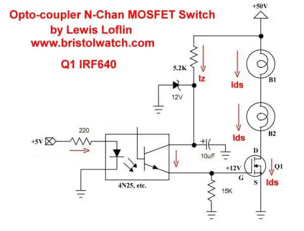
Fig. 1 N-channel opto-isolated MOSFET switching circuit using IRF630
High Voltage MOSFET Switching Circuits for H-Bridge Motor Controls
by Lewis Loflin
See the video High Voltage MOSFET Switch Tutorial
This page will discuss and review MOSFET power transistor switching circuits. The emphasis is higher voltage switching circuits. I'll be using the IRF630 and IRF9630 power MOSFETs. I'll also stress opto-coupler isolation of the power circuits from the microcontroller.
Fig. 1 uses the N-channel IRF630 with a 4N25 type opto-coupler. Note first the 5.2K resistor and 12-volt Zener diode. This provides 12-volts to turn on Q1 when the 4N25 transistor is switched on.
The Q1 gate-source voltage is limited to 20-volts and the 4N25 transistor collector breakdown voltage is limited to about 30-volts. This safely provides 12-volts to switch on Q1. Be aware the Q1 MOSFET is a voltage operated device and will store a charge due to gate-source capacitance.
The 15K gate bleeder resistor must be present for Q1 to turn off.
When +5V is applied to the opto-coupler input the internal LED switches on the output transistor. This switches +12-volts to Q1 gate turning on Q1, creating a current path for Ids.
When the opto-coupler is turned of the 15K gate-bleeder resistor turns off Q1.
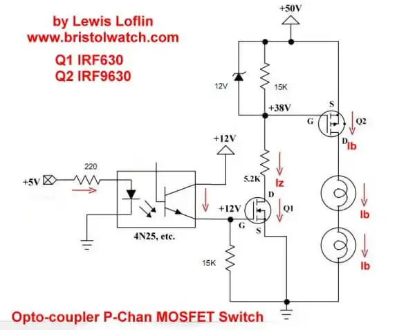
Fig. 2 P-channel opto-isolated MOSFET switching circuit using IRF9630
Fig. 2 shows how to use a P-channel IRF9630 MOSFET to switch the positive side of the power supply to the light bulbs acting as a load.
The input opto-coupler and Q1 operate the same as Fig. 1. While this show connections to a separate 12-volt supply, it can use the same resistor-Zener combination of Fig. 1.
I'm using a IRF630 MOSFET for Q1 because the high voltage in the Zener-resistor voltage divider circuit. When Q1 is switched of no current flows and we have no voltage drop across the Zener - Q2 is turned of.
When Q1 is switch on current flow Ik created a 12-volt difference across the Zener thus Q2 gate-source, turning Q2 on. The Zener diode limits Vgs on Q2 to under 20-volts.
As long as we have Ik Q2 will turn on. When Q1 is turned off Ik is turned off. The 15K gate bleeder resistor across the Zener discharges the Q2 gate turning off Q2.
Update Dec. 2019. Many micro-controllers today are using 3.3-volt Vcc. This is also true of Raspberry Pi. I found two MOSFETs that work at 3.3-volts.
The IRFZ44N is an N-channel device rated at 55V and RDS(on) resistance of 0.032 Ohms max. The other is a P-channel device rated at 55V and a RDS(on) of 0.02 Ohms max.
See the following spec sheets:
- N-Channel Power MOSFET Switching Tutorial
- P-Channel Power MOSFET Switch Tutorial
- H-Bridge Motor Control with Power MOSFETs
- More Power MOSFET H-Bridge Circuit Examples
- Build a High Power Transistor H-Bridge Motor Control
- Basic MOSFET Transistor Test Circuits
- High Voltage MOSFET Switching Circuits
- LM317 Adjustable Voltage, Current Boost Power Supply
- Constant Current Circuits LM334, LM317
- Build LM317 0-34 Volt Power Supply
- LM334 Constant Current Source with Resistive Sensors
- LM317 High Power Constant Current Source Circuit
- LM317 Constant Current Source Circuits
- Test SCRs and Triacs
- 3 Amp LM741 Op-Amp Constant Current Source
- Current Limiter Testing of Zener Diodes
- Current Limiter for Opto-Coupler Inputs
- LM317 CCS for Light Emitting Diodes
- Experiments with TL431 Shunt Regulator
- TL431A Precision Current Regulator Circuits
- TL431A Based Current Limiter Constant Current Source Circuits
- TL431A Shunt Regulator Circuits
- Using TL431A Li-Ion Battery Charger Tutorials
- TL431A Lithium-Ion Cell Charging Circuits
- Charging Multi-Cell Lithium-Ion Battery Packs
- TL431 Over-Voltage, Under-Voltage Detector Circuits
- TL431A Constant Current Source Working Circuits Demo
Related YouTube video TL431A Lithium-Ion Cell Charging Circuits
Related YouTube video TL431 Battery Charger Circuit Calculations Revised
Related YouTube video TL431 10-Volt Charger Short Version
Related YouTube video Charging, Charge-Balancing 18V Li-Ion Battery with TL431
Related YouTube video 18.5V Li-Ion Battery Charger with TL431 (short)
- Arduino Measures Current from Constant Current Source
- Constant Current Source Theory Testing
- Arduino Controlled Power Constant Current Source
You Tube Videos
- Adjustable LM317 High Power Current Source
- Current Boost LM317 Adj. Power Supply
- LM317 Constant Current Source Circuits
Other Circuits
- Hall Effect Magnetic Switches and Sensors
- Comparator Theory Circuits Tutorial
- ULN2003A Darlington Transistor Array with Circuit Examples
- Transistor-Zener Diode Regulator Circuits
- AC Power Supply Rectification
- Coils for Highly Selective Crystal Radio
- Neon (NE-2) Circuits You Can Build
- Photodiode Circuits Operation and Uses
- Photodiode Op-Amp Circuits Tutorial
Web site Copyright Lewis Loflin, All rights reserved.
If using this material on another site, please provide a link back to my site.