
Fig. 1 Sidac sawtooth generator.
Click for larger image.
SIDAC Operation and Trigger Circuits
by Lewis Loflin
A SIDAC, also called a silicon bilateral voltage triggered switch, has far greater power-handling capabilities than standard diacs. See my page on diacs.
Upon application of a voltage exceeding the SIDAC breakover voltage point, the SIDAC switches on through a negative resistance region to a low on-state voltage.
Conduction continues until the current is interrupted or drops below the minimum holding current of the device.
This is illustrated above in Fig. 1 above. The capacitor C is 0.47uF is charged with a Vin of 170-volts through R a 100K resistor.
When the voltage reaches the SIDAC breakover voltage, the capacitor quickly discharges through the SIDAC almost to zero volts. When the holding current is too low to maintain conduction and the SIDAC switches off. The process repeats.
Here I have used an ECG6418 with a breakover voltage (VBO) between 104 - 118 volts. Let us say VBO = 110 volts. What is time or period t?
X = 1 / ( 1 - ( VBO / Vin) ) = 1 / ( 1 - ( 110 / 170 ) ) = 1 / 0.353 = 2.833;
Time t = .00000047 * 100,000 * ln(2.833) = 48.94m Sec or 1 / t ~= 20Hz.
When I actually ran this the frequency as near as I could measure with cheap oscilloscope was 17Hz.
In addition VBO was perhaps 104 volts. Fairly close to the spec sheet considering the non-lab test setup I used.
At higher frequencies I had more errors from calculated versus actual. This is common in the real world of electronics.
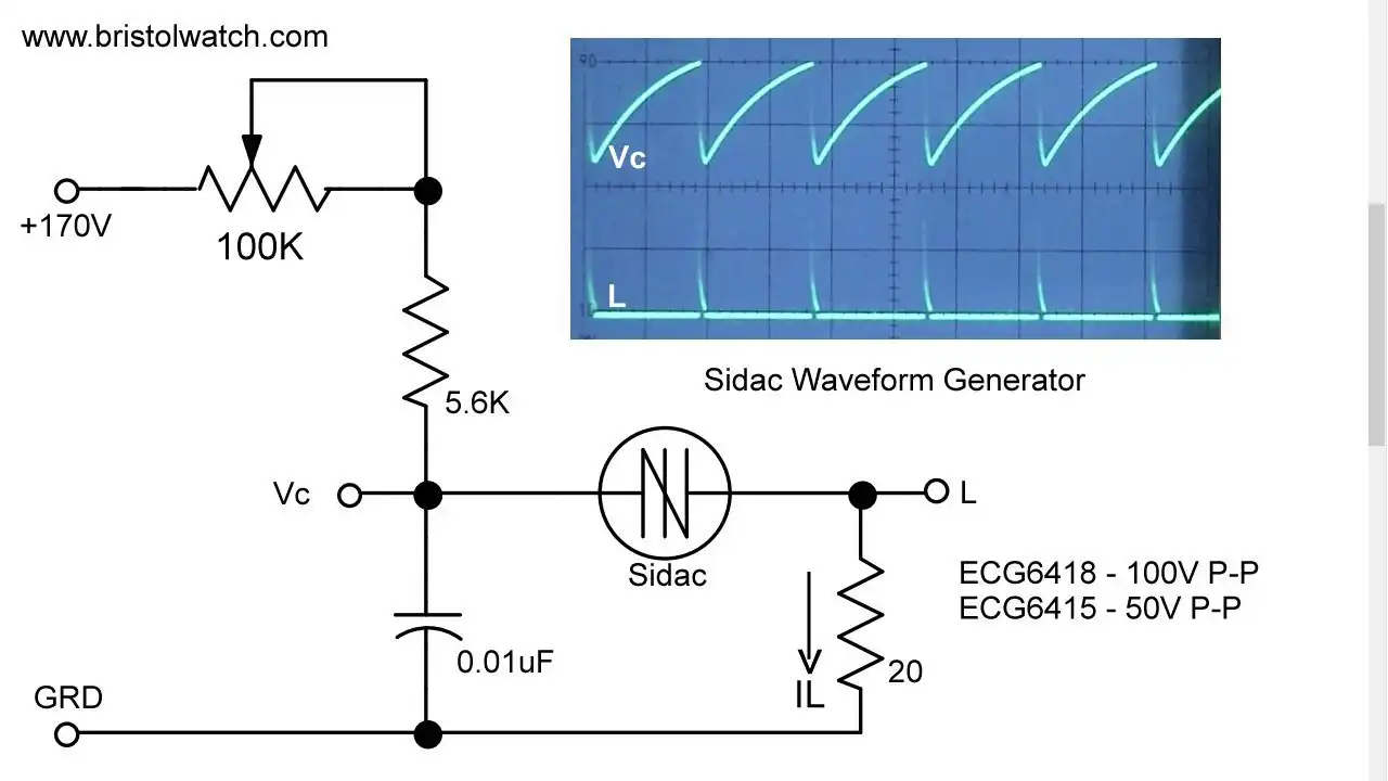
Fig. 1a SIDAC relaxation oscillator running several kilo Hertz.
Click for larger image.

Fig. 2 a sawtooth waveform as seen on my oscilloscope.
Click for larger image.
The peak-to-peak outputs are based on the SIDAC breakover voltage.
Using the NTE6415 (NTE has replaced ECG) the breakover voltage is around 45 - 60 volts, producing a ~50-volt P-P sawtooth waveform. Use of the a NTE6418 produces a 100-volt P-P sawtooth waveform. More on the technical specs of the devices I used is shown below.
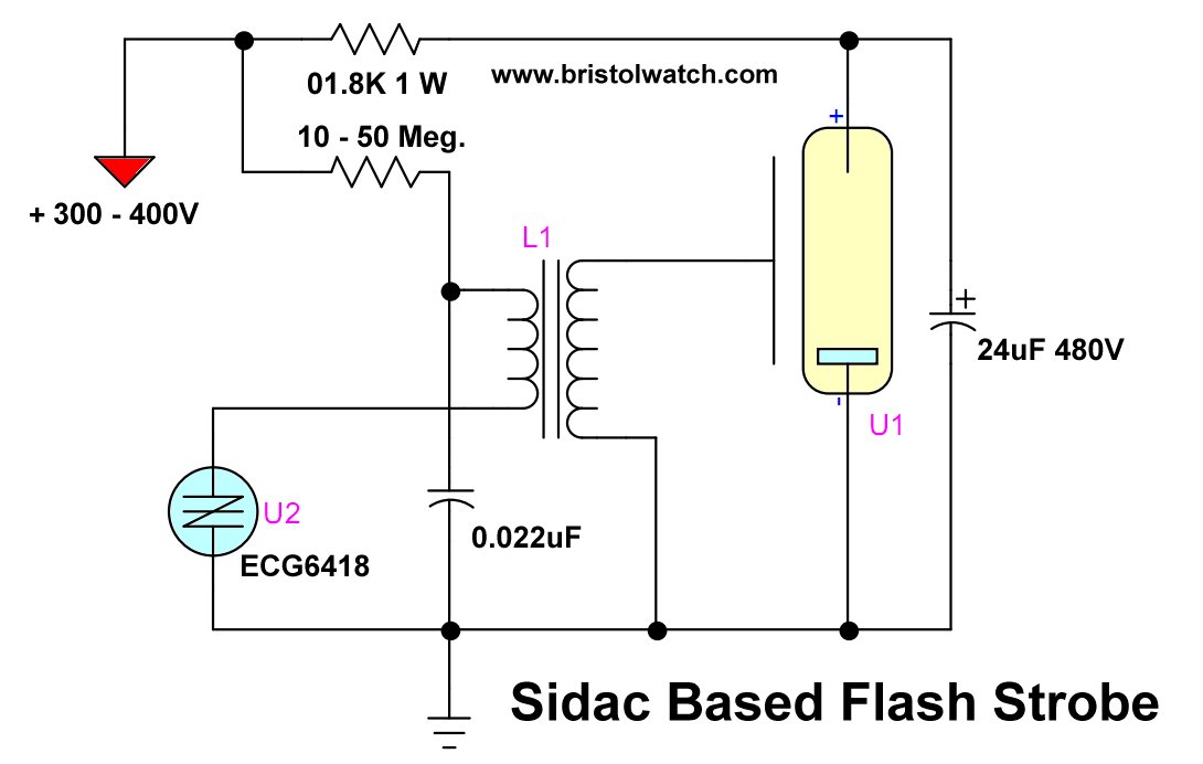
Fig. 3 using a SIDAC to operate a flash strobe.
Click for larger image.
When using low-power devices such as DIAC, we have to use a triac or SCR to handle higher power requirements. A SIDAC with its greater power capabilities can do the switching directly as shown above.
It's the same sawtooth generator as before, but the high current discharge from the capacitor is sent through a high-voltage trigger transformer. This 4-10KV pulse ionizes the gas in the tube allowing a 24uF capacitor to discharge through the xenon tube producing a bright flash.
Note that while I used a motor stat capacitor in this demo special photoflash capacitors that tolerate high discharge rates must be used.
The flash rate can be changed by altering the values of R and C (within limits) keeping in mind the photoflash capacitor has to charged trough a 1.8K resistor. See my page Using Xenon Flash Tubes.
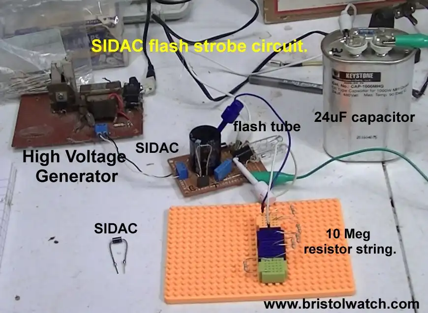
Fig. 4 SIDAC test setup.
Click for larger image.
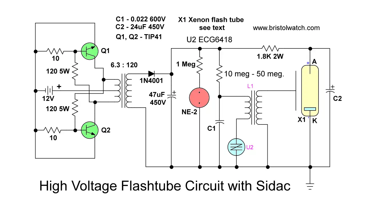
Fig. 5 SIDAC test setup complete schematic.
Click for larger image.
Related to this was a section on Unijunction transistor oscillators driving an SCR that switched on a higher current transformer. A SIDAC can replace this.
See the following:
- Understanding Unijunction Transistors Theory Operation
- Unijunction Transistor SCR Photo Flash Control Circuit
For information on the high voltage power supply used here see Build Autotransformer-Variac AC and DC Power Supply
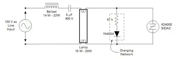
Fig. 4
Figure 4 illustrates the use of the higher power capabilities of a SIDAC to act as a solid-state starter for a fluorescent lamp.
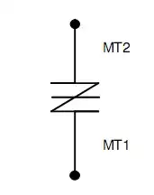
Fig. 5 SIDAC symbol.

Fig. 5 NTE Sidac specifications.
NTE6415 thru NTE6419 Bidirectional Thyristor Diodes (SIDAC)
Description:
The NTE6415 through NTE6419 SIDAC devices are silicon bilateral voltage triggered switches with
greater power handling capabilities than standard DIACS.
Upon application of a voltage exceeding
the SIDAC breakover voltage point, the SIDAC switches on through a negative resistance region to
a low on-state voltage. Conduction will continue until the current is interrupted or drops below the
minimum holding current of the device.
- Quick navigation of this website:
- Basic Electronics Learning and Projects
- Basic Solid State Component Projects
- Arduino Microcontroller Projects
- Raspberry Pi Electronics, Programming
- Load Lamp Safely Allows Safer Electronic Testing
- How to use SIDACs and Their Operation
- Build Autotransformer-Variac AC and DC Power Supply
- Warning About Electrical Shock and How to Prevent It
- Basic Triacs and SCRs
- Solid State AC Relays with Triacs
- Diac Waveform Generator, Trigger Circuits
- SIDAC Operation and Trigger Circuits
- Light Activated Silicon Controlled Rectifier (LASCR)
- Light Activated SCR Based Optocouplers Circuit Examples
- Comparing Photo Triac, Photo SCR Opto-Couplers
- Silicon Controlled Rectifier Review and Circuits
- Silicon Controlled Rectifiers Connected as Power Triacs
- Simple Triac-SCR Test Lab for You Tube
- AC Zero Crossing Detectors for Arduino
- Zero-Crossing Detectors Circuits
- Hardware Interrupts Demo and Tutorial for Arduino
- In Depth Look at AC Power Control with Arduino
- Arduino AC Power Control Using Interrupts
- Build Autotransformer-Variac AC and DC Power Supply
- Connecting Transformers in Series-Parallel
- Build an Adjustable 0-34 volt power supply with the LM317
- AC Power Supply Rectification
- Basic Power Transformers
- Transistor-Zener Diode Regulator Circuits
- Tips for the LM78XX Series Voltage Regulators
- Bi-Polar Power Supplies
- Connecting Series-Parallel Batteries
Web site Copyright Lewis Loflin, All rights reserved.
If using this material on another site, please provide a link back to my site.