Fig. 1
Tutorial MOSFET Output Solid State Relays
by Lewis Loflin
Here we will explore using photodiode-voltaic output opto-couplers to turn ON-OFF power MOSFET transistors. MOSFETs are voltage operated devices thus have very low power drive requirements.
We will look at both commercial units.
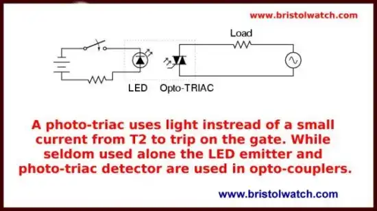
Fig 1 illustrates a typical solid state AC relay using a photo-triac and a LED emitter. The problem is these don't work on direct current because once turned on stay on until power is disrupted.
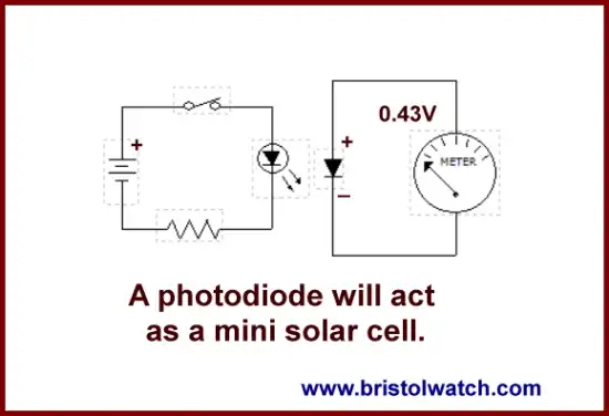
Fig. 2
Fig. 2 illustrates how a photodiode will generate a small voltage when exposed to light. For more on the basic operation see Photodiode Circuits Operation and Uses
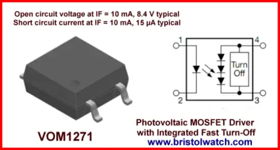
Fig. 3
In Fig. 3 we have the VOM1271 photovoltaic output opto-coupler. This uses a group of photodiodes in series to generate a usable output voltage. When the LED is turned on 7-10 volts is generated - the VOM1271 also includes a turnoff circuit (a gate bleeder resistor) to turn of the MOSFET when the LED is turned off.
There are a number of these devices available. See MOSFET DC Relays Using Photovoltaic Drivers.
The reason we use opto-couplers in general is to interface differing voltage levels, voltage isolation between high voltage sensors and low-voltage micro-controllers, and noise immunity. In these examples we isolate high voltage from a micro-controller such as Arduino.
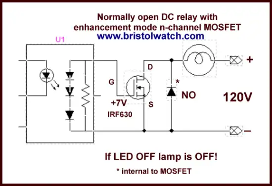
Fig. 4
Fig 4 shows the connections between a photovoltaic opto-coupler and an IRF630 N-channel power MOSFET. A microcontroller such as Arduino would treat the LED the same as any other LED. When the LED is switched on the photodiode array generates about 7-volts turning on the gate of the IRF630.
This is DC only - observe polarity! Voltage and current rating is determined by the MOSFET - the diode is internal to the MOSFET. Any number of MOSFETs can be used.
Also see Connecting Crydom MOSFET Output Solid State Relays.
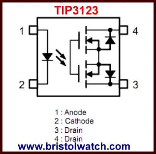
Fig. 5
Fig. 5 illustrates the TIP3123 solid state relay, a commercial device. What differs here is the use of two MOSFETs in addition to the photovoltaic opto-coupler circuit. The two output pins are connected to the MOSFET drains.
For more on MOSFETs see:
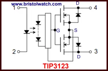
Fig. 6
The internal connections to the TIP3123 is shown in Fig. 6. We have our emitter LED and photodiode voltage array, the gates on the MOSFETs are tied together as are the source connections. The two open drain connections forms the output connections. The photodiode array is connected between the gate-source connections - both MOSFETs are turned on at the same time by the LED.
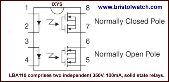
Fig. 7
The LBA110 is a dual SSR with a twist: the connections at pins 5 and 6 same as above with N-channel MOSFETs is N.O., while pins 7 and 8 form a normally closed (N.C.) relay. That is the relay is conducting when the LED at pins 1 and 2 is turned off.
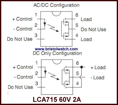
Fig. 8
Fig. 8 illustrates the LCA715 SSR rated at 60V at 2A. Like my two SSR circuits above the common source connection is brought out in pin 5 allowing two different ways to connect the device.
The top half of Fig. 8 shows the AC or DC connections - leave pin 5 disconnected.
The bottom half illustrates the DC only configuration with the open drains (pins 4 and 6) connected together and the load connected between them and pin 5. Observe polarity! This is N.O. mode only.
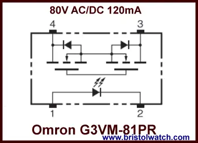
Fig. 9
Fig. 9 illustrates the G3VM-81PR rated at 80V AC/DC at 120mA. This is N.O. only and is a PC board mount device.
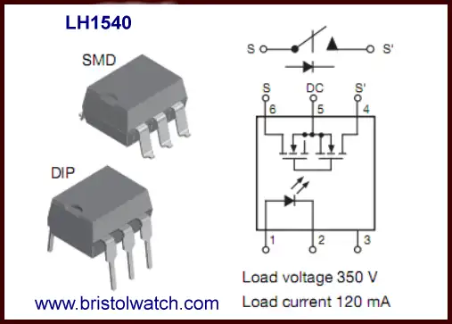
Fig. 10
Fig. 10 shows the LH1540 that brings out the common source to pin 5. This is rated at 360V AC/DC at 120mA. This can be connected for AC/DC or just DC only like Fig. 10. this is PC board mount either surface mount or through hole.
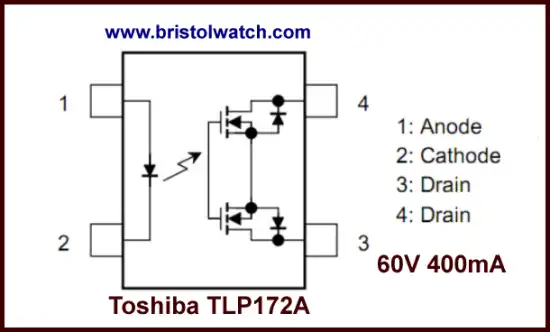
Fig. 11
Fig. 11 shows the TLP172 rated at 60V AC/DC at 400mA. This is surface mount only.
There are a great many solid state relays out there. Their lower cost and higher reliability will continue to replace older magnetic relays.
- Quick navigation of this website:
- Basic Electronics Learning and Projects
- Basic Solid State Component Projects
- Arduino Microcontroller Projects
- Raspberry Pi Electronics, Programming
- Comparator Theory Circuits Tutorial
- Zero-Crossing Detectors Circuits and Applications
- Improved AC Zero Crossing Detectors for Arduino
- Photodiode Circuits Operation and Uses
- Photodiode Op-Amp Circuits Tutorial
- Issues on Connecting MOSFETs in Parallel
- MOSFET DC Relays Using Photovoltaic drivers
- Optocoupler Input Circuits for PLC
- All NPN Transistor H-Bridge Motor Control
- Photo Voltaic Tutorial MOSFET Output Solid State Relays
- Optical Isolation of H-Bridge Motor Controls
- Design 10-Amp 2N3055 Based Power Switch
- TA8050P H-Bridge Motor Control
- Connecting Crydom MOSFET Solid State Relays
- H11L1, 6N137A, FED8183, TLP2662 Digital Output Optocouplers
Arduino
- Arduino
- Arduino PWM to Analog Conversion
- Arduino Analog Digital Conversion Voltmeter
- Better Arduino Rotary Encoder Sensor
- Simple 3-Wire MAX6675 Thermocouple ADC Arduino Interface
- Hall Effect Magnetic Switches and Sensors
- Transistor-Zener Diode Regulator Circuits
- Build an Adjustable 0-34 volt power supply with the LM317
- Coils for Highly Selective Crystal Radio
- Neon (NE-2) Circuits You Can Build
- Understanding Xenon Flashtubes and Circuits
- LM2575 Simple Switching Voltage Regulators
- Simple 2 Transistor LED Flasher Circuit
- Generating High Voltage with an Inductor
Web site Copyright Lewis Loflin, All rights reserved.
If using this material on another site, please provide a link back to my site.