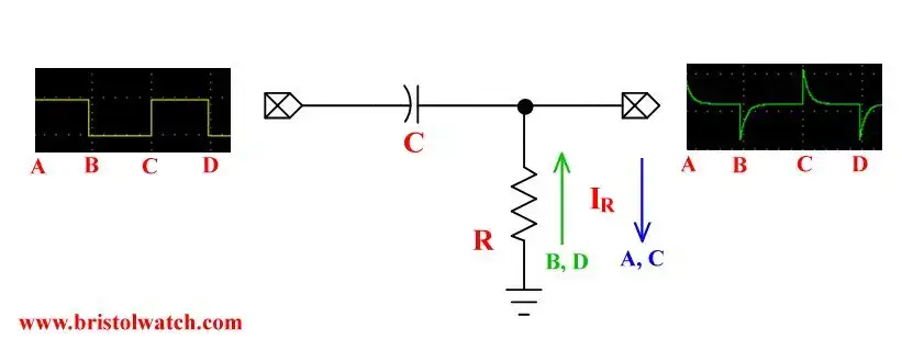
Fig. 1 Basic differentiator RC circuit.
Introduction to RC Differentiator Circuits and Uses
This is a tutorial on RC differentiator circuit operation. This is simply an RC timing circuit where the capacitor is on the input and the output is taken from the resistor.
I am assuming a 50% duty cycle square wave for input.
Fig. 1 illustrates the circuit in question. A square wave goes HIGH a rush of current (blue) to C through R creates a positive going spike. When C is fully charged the output voltage goes to zero.
When the input square wave goes LOW a rush of current in the opposite direction creating a negative going spike. This also goes back to zero when C fully discharges.
This charge or discharge curve is T = R * C - 5T is fully charged or discharged. If 5T is less than half the period (1/f) of the input C will fully charge-discharge. If 5T is greater than half the period, C will neither fully charge or discharge fully before the next change in logic voltage level.
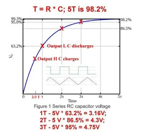
Fig. 2 Capacitor charge curve.
Fig. 2 illustrates a RC charge curve.
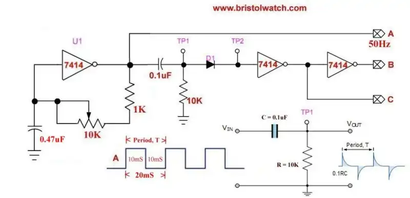
Fig. 3 SN7414 square wave generator and differentiator circuit.
Fig. 3 illustrates the use of a SN7414 square wave generator using a differentiator circuit to create narrow output pulses at points B and C.
Diode D1 is used to block the negative going pules to TP2.
Related:
Simple Schmitt Trigger SN7414 Square Wave Generator
Three Output Pulse Generator Circuit for Digital Circuits
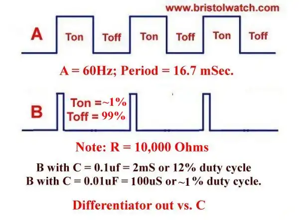
Fig. 4 Differentiator duty cycle versus RC value.
In Fig. 4 we observes the output waveform at point B versus the input to the differentiator circuit. The output pulse width and duty cycle is directly related to the value of C and a 10,000 Ohm resistor.
A value of C = 0.1uF produced a 12% duty cycle of 2 milliseconds.
A value of C = 0.01uF produces a very narrow pulse of 200 microseconds.
See Figures 5 and 6 below.

Fig. 5 A 2 millisecond pulse waveform at 12% duty cycle waveform.

Fig. 6 A 200 microsecond pulse at 2% duty cycle waveform.
The next 4 slides (7 through 10) illustrate the effect of increasing input frequency while C is fixed at 0.1uF and R = 10,000 Ohms. The slides are self explanatory. As the frequency increases C can neither fully charge or discharge. The output is a distorted square wave.
In Fig. 11 C was changed from 0.1uF to 0.01uF and even at 480 Hertz produced clean output spikes.
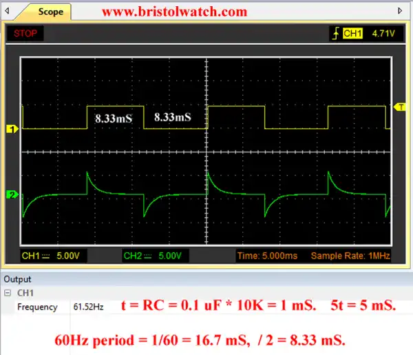
Fig. 7 RC differentiator circuit f = 60Hz C = 0.1uF.
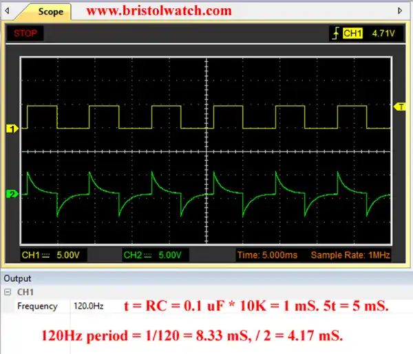
Fig. 8 RC differentiator circuit waveform f = 120Hz C = 0.1uF.
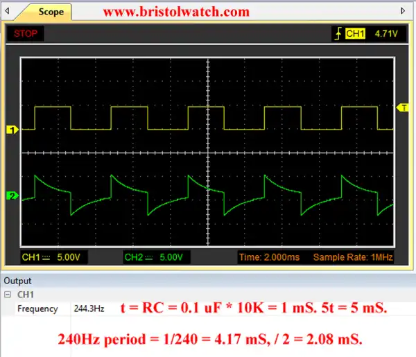
Fig. 9 RC differentiator circuit waveform f = 240Hz C = 0.1uF.
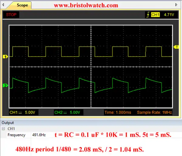
Fig. 10 RC differentiator circuit waveform f = 480Hz C = 0.1uF.
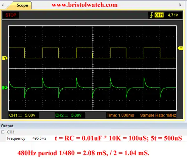
Fig. 11 RC differentiator circuit waveform f = 480Hz C = 0.01uF.
- Quick navigation of this website:
- Basic Electronics Learning and Projects
- Basic Solid State Component Projects
- Arduino Microcontroller Projects
- Raspberry Pi Electronics, Programming
- Digital Circuits:
- Simple Schmitt Trigger SN74HC14 Square Wave Generator
- Introduction to RC Differentiator Circuits and Uses
- SN74HC14 Square Wave Generator uses SN7476 JK Flip-Flop
- Three Output Digital Pulse Generator
- Astable CD4047 Geiger Counter Power Supply
- CD4047 Monostable Multivibrator Circuit
- Basic TTL Tri-State Buffer Circuit Examples
- Tutorial NOR Gate SR Latch Circuits
- Tutorial NAND Gate SR Latch Circuit
- Tutorial OR-NOR Circuits Monostable Multivibrator
- Tutorial of XOR and XNOR Logic Gates
Arduino
- Arduino
- Arduino PWM to Analog Conversion
- Arduino Analog Digital Conversion Voltmeter
- Better Arduino Rotary Encoder Sensor
- Simple 3-Wire MAX6675 Thermocouple ADC Arduino Interface
- Hall Effect Magnetic Switches and Sensors
- Transistor-Zener Diode Regulator Circuits
- Build an Adjustable 0-34 volt power supply with the LM317
- Coils for Highly Selective Crystal Radio
- Neon (NE-2) Circuits You Can Build
- Understanding Xenon Flashtubes and Circuits
- LM2575 Simple Switching Voltage Regulators
- Simple 2 Transistor LED Flasher Circuit
- Generating High Voltage with an Inductor
Web site Copyright Lewis Loflin, All rights reserved.
If using this material on another site, please provide a link back to my site.