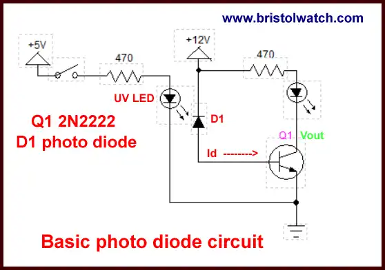
Fig. 1 My basic photodiode test circuit.
Photodiode Op-Amp Circuits
Here we will use operational amplifiers or op-amps to convert the photodiode current to a measurable voltage - this is called a trans impedance or current to voltage amplifier. This enable an analog-to-digital port on an Arduino or PIC microcontroller to measure light intensity.
Here in all cases the photodiode is reversed biased. We won't use the photodiode in it's voltaic mode. For more on these subjects see the following:
Fig. 1 shows a basic test circuit I constructed. When the LED is turned on reverse current flow through the photodiode from cathode to anode to the base of Q1. The current is amplified and use to light up a LED. This is an ON/OFF circuit useless for measuring light intensity.
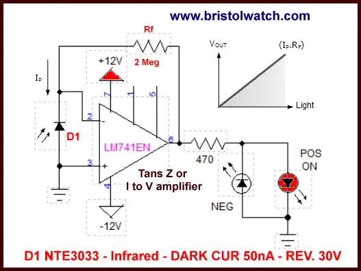
Fig. 2 basic LM741 photodiode trans-impedance amplifier.
In Fig. 2 we use a LM741 to convert the small leakage current to a voltage by the formula Rf * Ip. Depending on the value of Rf the voltage output is positive 0 to 10 volts. the brightness of the LED is proportional to light intensity on the photodiode.
Note this is a bipolar power supply circuit.
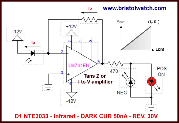
Fig. 3
Fig 2 differs in that the anode of the photodiode is connected to the -12 volt supply. This reduces capacitance and improves switching response. Note this is a demo circuit - for real high speed performance use high speed op-amps such as a Analog Device ADA4817-1 or Burr-Brown OPA640. Also use a PIN photodiode.
For more on photodiode capacitance see: Photodiode Circuits Operation and Uses
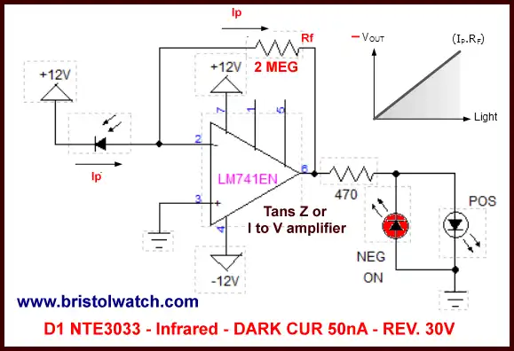
Fig. 4
In Fig. 4 we connect the cathode of the photodiode is connected to the +12 volt supply. This produces a negative voltage output. This is another bipolar power supply circuit.
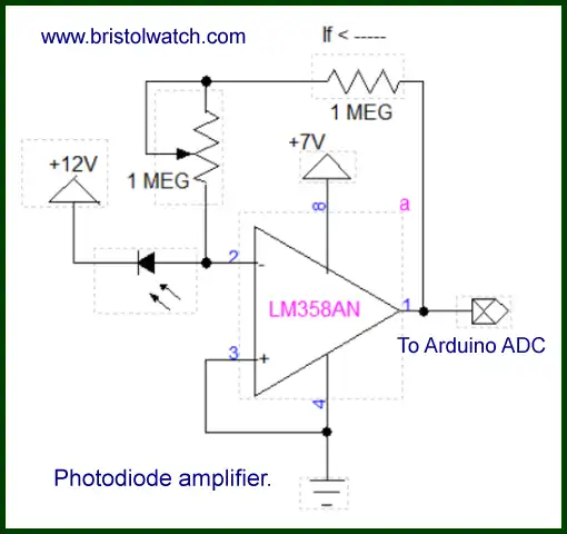
Fig. 5
Here is an experimental circuit to read light intensity with a photodiode with and Arduino. The maximum voltage out is 5-volts with a 7-volt supply. Output 0-5 volts.
This is a unipolar circuit.
Also see Optimizing Precision Photodiode Sensor Circuit Design by Analog Devices. (PDF)
- Quick navigation of this website:
- Basic Electronics Learning and Projects
- Basic Solid State Component Projects
- Arduino Microcontroller Projects
- Raspberry Pi Electronics, Programming
- Comparator Theory Circuits Tutorial
- Zero-Crossing Detectors Circuits and Applications
- Improved AC Zero Crossing Detectors for Arduino
- Photodiode Circuits Operation and Uses
- Photodiode Op-Amp Circuits Tutorial
- Issues on Connecting MOSFETs in Parallel
- MOSFET DC Relays Using Photovoltaic drivers
- Optocoupler Input Circuits for PLC
- All NPN Transistor H-Bridge Motor Control
- Photo Voltaic Tutorial MOSFET Output Solid State Relays
- Optical Isolation of H-Bridge Motor Controls
- Design 10-Amp 2N3055 Based Power Switch
- TA8050P H-Bridge Motor Control
- Connecting Crydom MOSFET Solid State Relays
- H11L1, 6N137A, FED8183, TLP2662 Digital Output Optocouplers
- Arduino
- Arduino PWM to Analog Conversion
- Arduino Analog Digital Conversion Voltmeter
- Better Arduino Rotary Encoder Sensor
- Simple 3-Wire MAX6675 Thermocouple ADC Arduino Interface
- Hall Effect Magnetic Switches and Sensors
- Transistor-Zener Diode Regulator Circuits
- Build an Adjustable 0-34 volt power supply with the LM317
- Coils for Highly Selective Crystal Radio
- Neon (NE-2) Circuits You Can Build
- Understanding Xenon Flashtubes and Circuits
- LM2575 Simple Switching Voltage Regulators
- Simple 2 Transistor LED Flasher Circuit
- Generating High Voltage with an Inductor
Web site Copyright Lewis Loflin, All rights reserved.
If using this material on another site, please provide a link back to my site.