Raspberry Pi and the 8-Digit LED MAX7219 Display Driver
The program presented below will allow Raspberry in Python and setup a MAX7219 display driver to act as a four digit counter. The program was ported over from Arduino C to illustrate how coding can be reused.
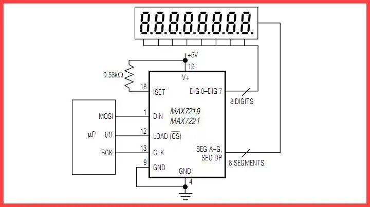
The MAX7219 display driver can drive 8 digit multiplexed LED display or a 8X8 LED matrix. This is setup in software. It includes selectable internal binary-coded-decimal (BCD) decoding which is used here.
It can also be cut on/off by a single command, the number of digits displayed, and intensity are all selectable in software. See "def initMAX7219()" below.
Refer to the block diagram above. 16-bit data input is broken into 2 8-bit data bytes the first being an address and the second being data. Using the function writeMAX7219(digit, k) digit is the digit value and k is position pointer.
For example assuming BCD mode and digit = 1 and k = 1 a one will be displayed on the far right of the display. writeMAX7219(digit, k) uses ssrOut() twice.
BCD code is limited to 0-9. Here we take a for loop where i counts from 0-999. Each iteration the value of i is sent to j which the MOD function j with 10 returns remainder value of 0-9.
The position and value are output to the display. The j is then divided by 10. This done 4 times to cover all four digits. Then i will increment and the process will begin again.
In the next section we will use the Python time and datetime function to create a LED real time clock.
See Raspberry Pi Python RTC with MAX7219 Display Driver
The code is rpi_count1.txt
- Quick navigation of this website:
- Basic Electronics Learning and Projects
- Basic Solid State Component Projects
- Arduino Microcontroller Projects
- Raspberry Pi Electronics, Programming
- LM334 CCS Circuits with Thermistors, Photocells
- Photodiode Circuits Operation and Uses
- Photodiode Op-Amp Circuits Tutorial
- Electronics hacks:
- Connecting PCF8574P GPIO Expander to Raspberry Pi
- Programming PCF8574P 8-bit I-O Expander with Arduino
- Connect-Program Raspberry Pi and a MM5451 LED Display Driver
- Raspberry Pi Python RTC with MAX7219 Display Driver
- Raspberry Pi and the 8-Digit LED MAX7219 Display Driver
- Programming Raspberry Pi and the 74HC595 Serial Shift Register
- Interface I2C LCD to Raspberry Pi in C
- ADS1115 4-Channel ADC Uses I2C with Raspberry Pi
- MCP4725 12-Bit DAC Interface to Raspberry Pi
- WiringPi and Pulse-Width-Modulation with Raspberry Pi
- WiringPi for Raspberry Pi and MAX6675 thermal-couple sensor
- WiringPi Blink an LED Demo
- Simple GPIO Reference Box
- Raspberry Pi with PCF8591 Analog To Digital Control in C
- Raspberry Pi PCF8591 AD-DA Sensor Python Interface
- Digital Circuits:
- Simple Schmitt Trigger SN74HC14 Square Wave Generator
- Introduction to RC Differentiator Circuits and Uses
- SN74HC14 Square Wave Generator uses SN7476 JK Flip-Flop
- Three Output Pulse Generator Circuit for Digital Circuits
- Astable CD4047 Geiger Counter Power Supply
- CD4047 Monostable Multivibrator Circuit
- Basic TTL Tri-State Buffer Circuit Examples
- Tutorial NOR Gate SR Latch Circuits
- Tutorial NAND Gate SR Latch Circuit
- Tutorial OR-NOR Circuits Including Monostable Multivibrator
- Brief Tutorial of XOR and XNOR Logic Gates
- LM555-NE555 One-Shot Multivibrator AC Power Control
- Arduino
- Arduino PWM to Analog Conversion
- Arduino Analog Digital Conversion Voltmeter
- Better Arduino Rotary Encoder Sensor
- Simple 3-Wire MAX6675 Thermocouple ADC Arduino Interface
- Hall Effect Magnetic Switches and Sensors
- Basic Hall Effect Sensors YouTube
- Opto-Isolated Transistor Drivers for Micro-Controllers
- Opto-Couplers Theory and Circuits YouTube
- H-Bridge Motor Control with Power MOSFETs Updated
- Build Power MOSFET H-Bridge for Arduino YouTube
- LM317 High Power Constant Current Source Circuit
- Adjustable LM317 High Power Current Source
- ULN2003A Darlington Transistor Array with Circuit Examples
- ULN2003A Transistor Array with Arduino
- Constant Current Circuits with the LM334, LM317
- Constant Current Source Tutorial YouTube
- N-Channel Power MOSFET Switching Tutorial
- P-Channel Power MOSFET Switch Tutorial
- Using Power MOSFETs with Arduino YouTube
- Zero-Crossing Detectors Circuits and Applications
- Zero-Crossing Circuits for AC Power Control
- In Depth Look at AC Power Control with Arduino
- Micro-controller AC Power Control Using Interrupts
- YouTube Video for Arduino AC Power Control
- All NPN Transistor H-Bridge Motor Control
- All NPN Transistor H-Bridge Motor Control YouTube
Web site Copyright Lewis Loflin, All rights reserved.
If using this material on another site, please provide a link back to my site.