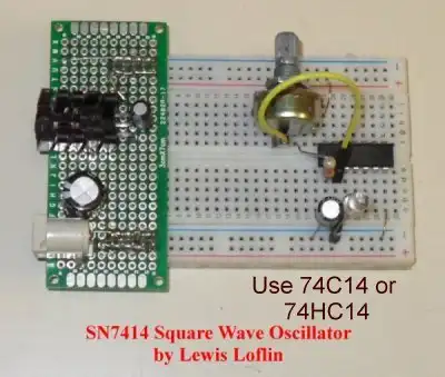
Simple Schmitt Trigger SN74HC14 Square Wave Generator
Make sure to use a SN74C14 or SN74HC14.
Theory and practical circuits on using a Schmitt Trigger based SN74HC14 square wave oscillator.
YouTube video: Simple Schmitt Trigger SN74HC14 Square Wave Generator
In Vol. 63 June/July Make Magazine Charles Platt wrote an article on using a SN74HC14N Schmitt Trigger HEX inverter. Using only one of six inverters, a capacitor, and feedback resistor, he created a basic square-wave oscillator.
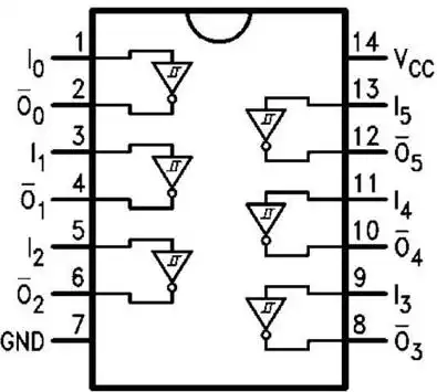
Fig. 1 SN74HC14 internal connections.
He didn't go into detail on calculating component values or much on the theory of operation. Here I'll expand on that. Fig. 1 is the internal connections on the device. Note in the following schematics I will not show +Vcc pin 14 or ground pin 7. +Vcc is 5-volts, a HIGH is 5-volts and a LOW is 0 volts.
I will be dealing with a single inverter and all measurements are based on a live circuit built from real components. I do not use SPICE or simulation software and can't guarantee its operation with such software.
Measurements are taken with a Radio Shack 22-812 digital multimeter that can measure frequency, pulse-width, and duty cycle.
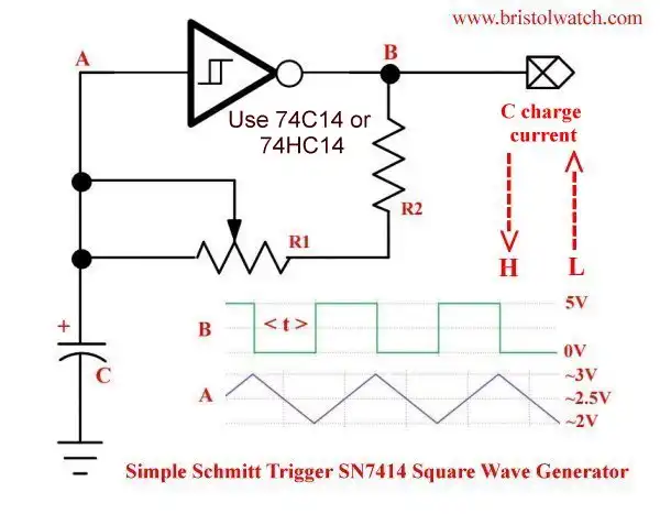
Fig. 2 SN74HC14N Square wave oscillator circuit.
Fig. 2 illustrates the circuit I'll be using. It consists of a single inverter, feedback resistance, and a charge capacitor. Let us discuss the difference between a Schmitt Trigger versus non-Schmitt Trigger inverter.
Very simply an inverter inverts the input logic level - HIGH in LOW out, LOW in HIGH out. The problem becomes at what voltage level from 0V to 5V is HIGH or LOW? What is 2.5 volts?
Schmitt Trigger inputs solve this problem for noisy circuits. A LOW is output only when the input 3-volts or greater. A HIGH is output only when the input is 2-volts or less. The level switches only if below ~2V or above ~3v.
In Fig. 2 refer to waveforms at points A and B. When powered on input A is LOW while B is HIGH; capacitor C charges up from the HIGH output through R1 and R2.
When A reaches ~3-volts B goes low and C discharges back through R1 and R2 into the output of the inverter. In reality when HIGH is output when an internal transistor switches to +Vcc, a LOW used a transistor to switch to ground.
The triangle waveform on A charges/discharges between ~2-volts and ~3-volts or ~1-volt peak-to-peak.. The output is 5-volts peak to peak. The capacitor C never fully charges to +Vcc or fully discharges to GRD. This 1-volt switching gap is the secret behind the oscillator.
Note the two red arrows. C charges when B is HIGH and discharges when B is LOW.
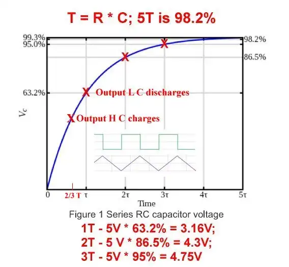
Fig. 3 RC charge curve.
Fig. 3 is our RC charge curve. When a capacitor is charged though a resistor time T depends of the values of R and C or R * C. But to be fully charged is 5T. If C = 1uF and R = 10K then T = .0000001 * 10,000 = 0.01 Sec. or 10 mSec. To be fully charged or 98.2% takes 50 mSec.
Note: always convert C to farads. Let's assume 1uF and 10K.
During the 1T C charges up to 63.2%. In the case of 5-volts that's ~3.16 volts. Only when first energized t = 10 mSec. and at 3.16V the output of the inverter goes LOW or 0V.
As C discharges to ~2 volts the out B goes HIGH charging capacitor C back to ~3 volts, etc.
As far as the output is concerned on/off T switches from 2/3T to 1T on the input. To calculate T on the output is (R * C) / 2.8. I derived this by experimentation.
So each on/off half period is 10 mSec. / 2.8 = 3.57 mSec. To get the frequency of the output square wave = 3.57 mSec. * 2, then take the reciprocal. In this case 140Hz.
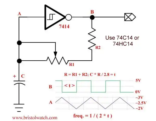
Fig. 4 SN74HC14N Square wave oscillator circuit with formulas.
Fig. 4 shows the formulas for this circuit. I going to calculate values as used in a live circuit the measure the values on my multimeter. I used a 22K resistor that measured 21,700 Ohms. I also measured the capacitors used.
Example 1: C = 1uF; R = 21,700 Ohms.
R * C = 21.7mSec.; t = 21.7 mSec. / 2.8 = 7.75 mSec.
f = 1 / (2 * t) = 1 / 15.5 mSec. = 64.5Hz
Measured value = 63.3Hz error 2%; duty cycle 47%. Very close to a symmetrical square wave.
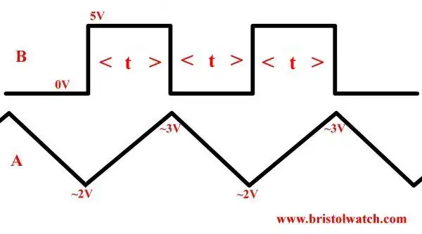
Fig. 5 SN74HC14N Square wave oscillator circuit waveforms.
Example 2: C = 34.72uf; R = 21,700 Ohms.
R * C = 0.7534 Sec.; 0.7534 Sec. / 2.8 = .2691 Sec. = t
f = 1 / (2 * t) = 1 / 0.53816 = 1.86Hz.
Measured value 1.9Hz error 2%; 47% duty cycle.
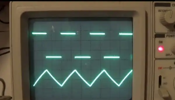
Fig. 6 SN74HC14N Square wave oscillator circuit waveforms on oscilloscope.
Fig. 6 based on example 3.
Example 3: C = 0.095uF; R = 21,700 Ohms.
R * C = 2.06 mSec; 2.06 mSec / 2.8 = 0.736 mSec. = t
f = 1 / (2 * t) = 1 / 1.4725 mSec. = 679Hz.
Measured: 707Hz, error 4%. 47% duty cycle. Note stray capacitance in the breadboard, etc. would possibly come into play at lower values of C.
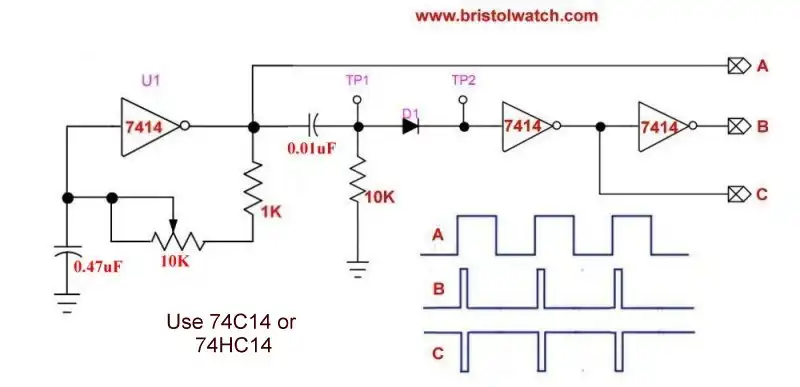
Fig. 7 SN74HC14 based square wave generator with differentiator circuit.
For more on this circuit see Three Output Pulse Generator Circuit for Digital Circuits.
Have fun.
- Quick navigation of this website:
- Basic Electronics Learning and Projects
- Basic Solid State Component Projects
- Arduino Microcontroller Projects
- Raspberry Pi Electronics, Programming
- Digital Circuits:
- Simple Schmitt Trigger SN74HC14 Square Wave Generator
- Introduction to RC Differentiator Circuits and Uses
- SN74HC14 Square Wave Generator uses SN7476 JK Flip-Flop
- SN74C14 Three Output Pulse Generator Circuit
- Astable CD4047 Geiger Counter Power Supply
- CD4047 Monostable Multivibrator Circuit
- Basic TTL Tri-State Buffer Circuit Examples
- Tutorial NOR Gate SR Latch Circuits
- Tutorial NAND Gate SR Latch Circuit
- Tutorial OR-NOR Circuits Including Monostable Multivibrator
- Brief Tutorial of XOR and XNOR Logic Gates
- LM555-NE555 One-Shot Multivibrator AC Power Control
- YouTube:
- Three Output Digital Pulse Generator
- Digital Circuits:
- Two Transistor LED Flasher Circuit
- Astable CD4047 Geiger Counter Power Supply
- CD4047 Monostable Multivibrator Circuit
- Basic TTL Tri-State Buffer Circuit Examples
- Tutorial NOR Gate SR Latch Circuits
- Tutorial NAND Gate SR Latch Circuit
- Coils for Highly Selective Crystal Radio
- Neon (NE-2) Circuits You Can Build
- Understanding Xenon Flashtubes and Circuits
Web site Copyright Lewis Loflin, All rights reserved.
If using this material on another site, please provide a link back to my site.