Tri-State H-Bridge
From Basic Digital Circuits to H-Bridge Motor Controls
by Lewis Loflin
Related page Exploring Solid State Relays and Control Circuits.
Introduction - The purpose of these pages is to introduce the student and hobbyist to electronics projects. My hope is generate interest for those thinking about entering a high tech field, or simply to have fun.
I'm presenting working circuit examples. Videos and related links will go into detailed explanations.
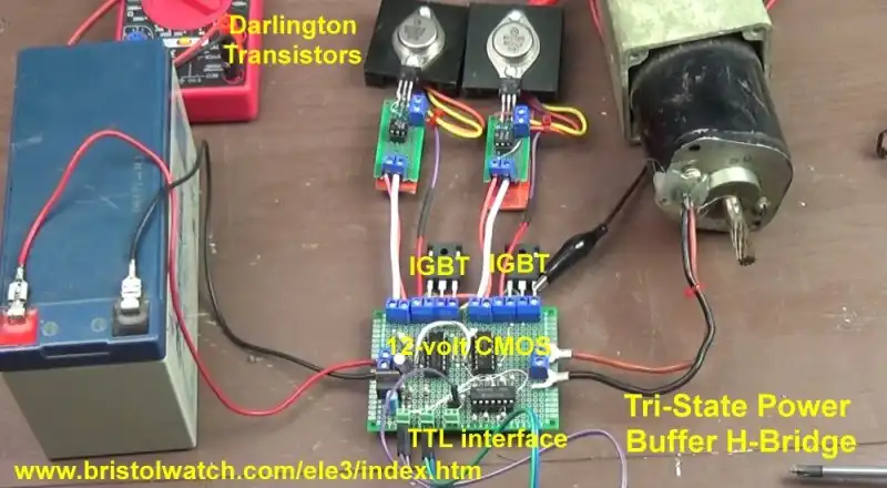
Fig. 1
Some basic terms
I'll define terms for beginners. A HIGH is a binary or logical 1. In binary we only have 1s and 0s. A HIGH or simply H is an electrical voltage of 3-15 volts depending on the logic family. a LOW or L is zero volts.
An overview of some logic families:
74XX is power hungry and slow response time. Vcc is 5 volts.
74LSXX are much faster but still power hungry. Vcc is 5 volts.
74CXX are built from CMOS not bipolar transistors. The voltage range is 3-15 volts. Power consumption is low.
74HCXX is fast, low power. Vcc = 2-6 volts. Speed varies by voltage.
CD4XXX is low power, slow. Vcc = 3-15 volts.
Slow or fast are relative terms. Often this means time delay from input to output reaction. 10-3 is milliseconds or 1 / 1000 second. 10-6 is microseconds or 1 / 1,000,000 second.
Nanoseconds is 10-9 second or 0.001 microsecond. A 74LS14 HEX Schmitt trigger inverter operates at 15 nano seconds. A 74HC14 operates at 55 nanoseconds at 2 volts and 11 nanoseconds at 6 volts.
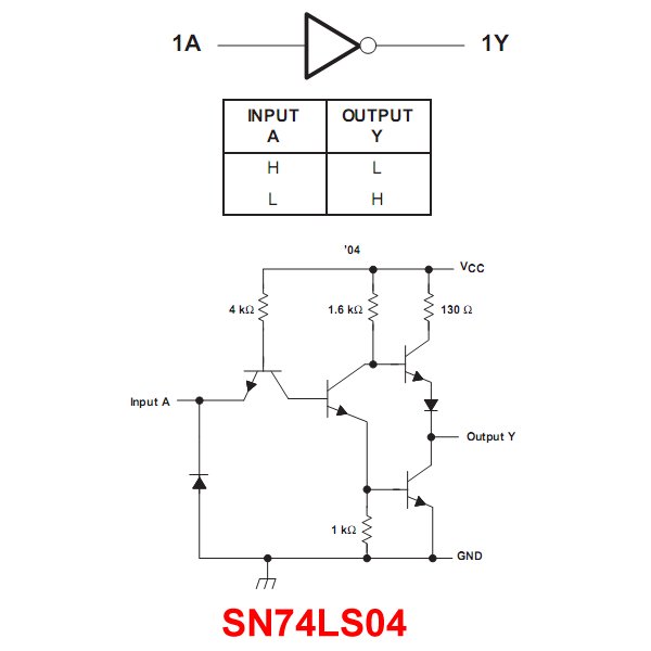
In my tutorials I'll be using the 74LSXX series of digital circuits. They have been around for decades and operate at 5 volts. They are built from bipolar transistors. See for example the 74LS04 Hex Inverters.
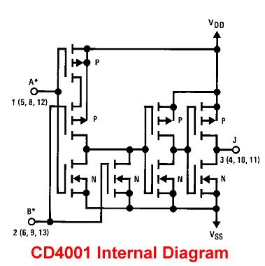
These are TTL or transistor-transistor logic. Compare the above with a typical CD4XXX type gate. See CD4001 Internal Diagram.
An inverter simply changes a HIGH to LOW or a LOW to a HIGH. Again see 74LS04 Hex Inverters.
Most of the integrate circuits I'll like the 74LS04 above uses totem pole outputs to save power. If the output is HIGH the upper transistor was switch ON to connect to Vcc. If the output is low the bottom transistor switches on to ground.
Contrast this with 74LS06 also an inverter but has an open collector output. It requires an external load and can only switch to ground. See 74LS06 Hex Inverters Open Collector 30-Volts.
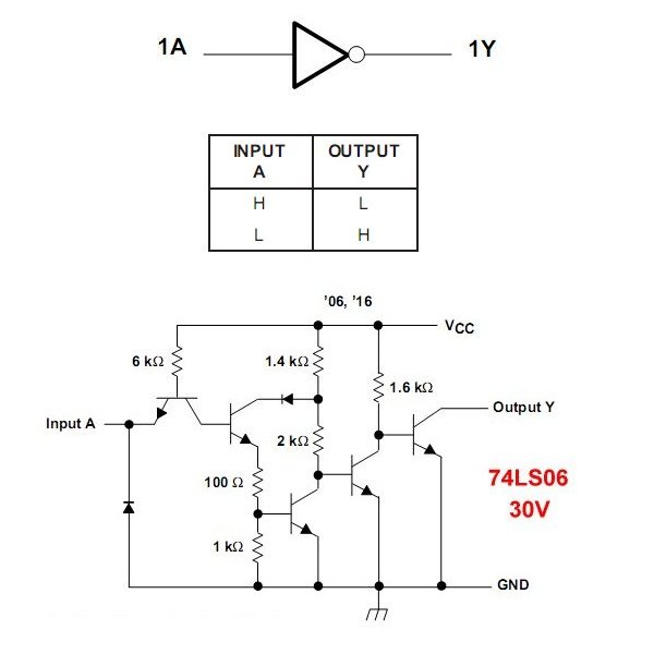
See the graphic 74LS04 versus 74LS06.
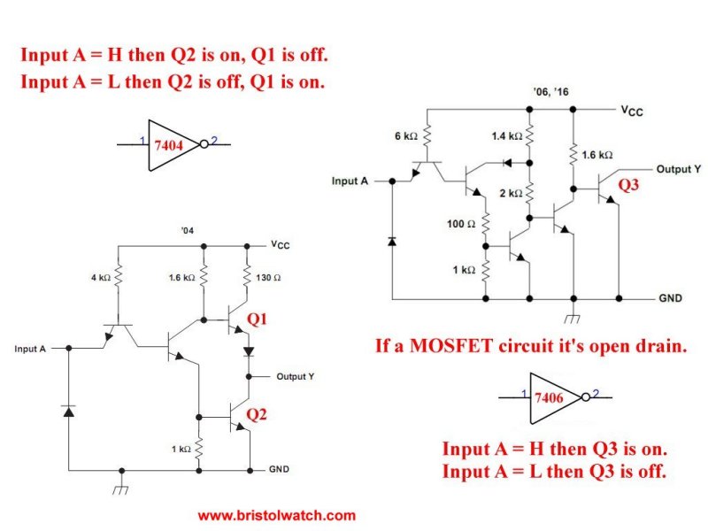
This can be used to connect to higher voltage loads to the 5 volts Vcc of the device. An example is TTL logic can connect to higher voltage CMOS logic. The 74LS06 is inverting, the 74LS07 is non-inverting.
When an output switches to Vcc or the power supply we call this "sourcing" the current. When the output switches to ground we call this "sinking" the Current. Bipolar transistors are current operated devices. CMOS transistors are voltage operated.
A buffer is designed to drive multiple inputs on other gates. It provides more current capability. Often called fan out most will drive 2 TTL loads.
A 74LS02 has a standard totem pole output and will source two TTL loads. A 74LS28 has a fan out of 30 TTL loads. Both are quad, 2-input NOR gates with identical electrical connections. I'll be using a number of 74LS02 quad NOR gates. A NOR outputs a LOW if any input is HIGH. See 74LS02 Quad 2-Input NOR Gates
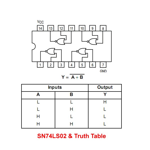
A 74LS32 is a quad, 2-input OR gates or non-inverting ORs. Any HIGH input is a HIGH output. A 74LS02 is a quad, 2-input NOR gates or inverted ORs.
A NAND gate is an inverted state AND gate. An AND gate has at least two inputs. The output is a HIGH when all inputs are HIGH, otherwise output is LOW. If any input is LOW the output is LOW. An inverted AND or NAND has the output reversed. All inputs HIGH the output is LOW. Otherwise the output is HIGH
I'll be using the 74LS00 NAND gate and the 74LS08 AND gate. Each 14 pin integrated circuit has 4, 2-input gates. The pin connections are identical. See 74LS00 Quad 2-Input NAND Gates.
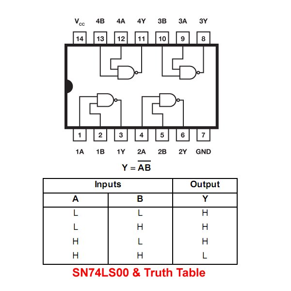
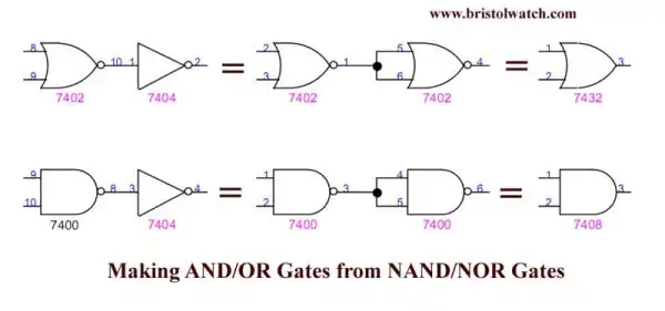
The figure above illustrates how to use NOR or NAND gates to create an inverter, an OR, or an AND gate.
Also see the illustration for Converting 4-input NAND-AND Gates.
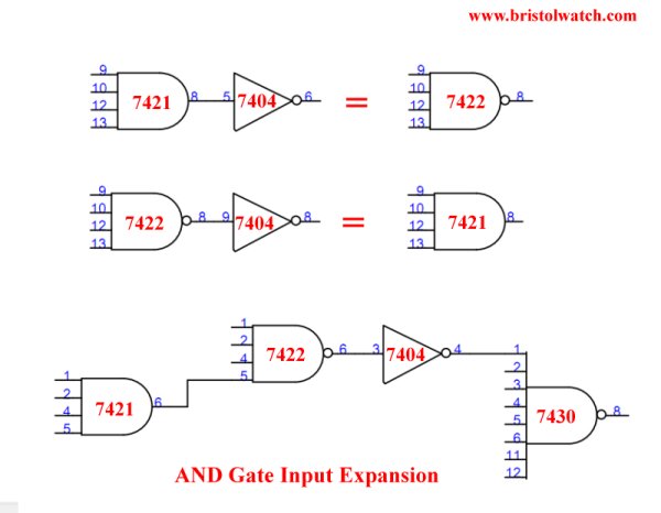
- Test Power MOSFET Transistors, IGBTs Results, Observations
- High current TTL MOSFET Driver Circuit
- Insulated Gate Bipolar Transistor IGBT Circuits
- Optocouplers for TTL-CMOS Logic Level Shifting
- Light Activated SCR Based Optocouplers Circuit Examples
- Bidirectional Solid State Relay Circuits
- Build High Power MOSFET Bidirectional Switch Relay
- Digital Circuits
- Basic TTL Tri-State Buffer Circuit Examples
- Tutorial NOR Gate SR Latch Circuits
- Tutorial NAND Gate SR Latch Circuit
- Constant Current Source
- Constant Current Circuits with the LM334
- Current Limiter Allows Safe Testing of Zener Diodes, LEDs
- 3 Amp LM741 Op-Amp Constant Current Source
- Current Limiter Circuits for Opto-Coupler Input LEDs
- Why Your MOSFET Transistors Get Hot
- H-Bridge Driving Large Motor YouTube
- Issues on Connecting MOSFETs in Parallel YouTube
- Simple Circuits for Testing MOSFET Transistors YouTube
- Three Output Digital Pulse Generator
- Light Activated SCR Based Optocouplers Circuit Examples
- Comparing Photo Triac, Photo SCR Opto-Couplers
- Silicon Controlled Rectifier Review and Circuits
- Silicon Controlled Rectifiers Connected as Power Triacs
- Exploring Solid State Relays and Control Circuits
- Comparing Photo Triac, Photo SCR Opto-Couplers
- Light Activated SCR Based Optocouplers Circuit Examples
- Silicon Controlled Rectifier Review and Circuits
- Silicon Controlled Rectifiers Connected as Power Triacs
- Insulated Gate Bipolar Transistor IGBT Circuits
- Current Limiter Circuits for Opto-Coupler LEDs
- VOM1271 Photovoltaic MOSFET Driver Circuits
- Current Limiter Allows Safe Testing of Zener Diodes, LEDs
- 3 Amp LM741 Op-Amp Constant Current Source
- Bidirectional Solid State Relay Circuits
- Simple Solid State Relay for Low Power LED 120V Lamps
- Build High Power MOSFET Directional Switch Relay
- Optical Isolation of H-Bridge Motor Controls
- All NPN Transistor H-Bridge Motor Control
- Basic Transistor Driver Circuits for Micro-Controllers
- ULN2003A Darlington Transistor Array with Circuit Examples
- Tutorial Using TIP120 and TIP125 Power Darlington Transistors
- Driving 2N3055-MJ2955 Power Transistors with Darlington Transistors
- Understanding Bipolar Transistor Switches
- N-Channel Power MOSFET Switching Tutorial
- P-Channel Power MOSFET Switch Tutorial
- Build a Transistor H-Bridge Motor Control
- H-Bridge Motor Control with Power MOSFETS
- More Power MOSFET H-Bridge Circuit Examples
- Build a High Power Transistor H-Bridge Motor Control
- H-Bridge Motor Control with Power MOSFETS Updated
- Opto-Isolated Transistor Drivers for Micro-Controllers
- Comparator Theory Circuits Tutorial
- Constant Current Circuits with the LM334
- LM334 CCS Circuits with Thermistors, Photocells
- LM317 Constant Current Source Circuits
- TA8050P H-Bridge Motor Control
- All NPN Transistor H-Bridge Motor Control
- Basic Triacs and SCRs
- Comparator Hysteresis and Schmitt Triggers
- Comparator Theory Circuits Tutorial
- Photodiode Circuits Operation and Uses
- Optocoupler MOSFET DC Relays Using Photovoltaic drivers
- Connecting Crydom MOSFET Solid State Relays
- Photodiode Op-Amp Circuits Tutorial
- Optocoupler Input Circuits for PLC
- H11L1, 6N137A, FED8183, TLP2662 Digital Output Optocouplers
- Optical Isolation of H-Bridge Motor Controls
- All NPN Transistor H-Bridge Motor Control
© Copyright 2019 Lewis Loflin E-Mail