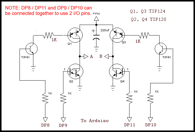
Darlington transistor H-Bridge
Build H-Bridge Motor Control Without Fireworks
Link to YouTube video for this webpage: H-Bridge construction.
This is a shorter version of Safely Build Program a H-Bridge using a MOSFET H-Bridge less focused on programming.
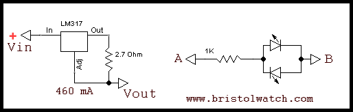
LM317 constant current source.
The two items above serve the following purposes: limit the current so wiring mistakes or bad programming won't blow your transistors or MOSFETs. The other is simple LED polarity indicator to show the polarity is switching - make sure this works BEFORE connecting a motor!
Make sure any H-bridge is connected to a microcontroller, not push button switches, etc.
Also see LM317 Constant Current Source Circuits
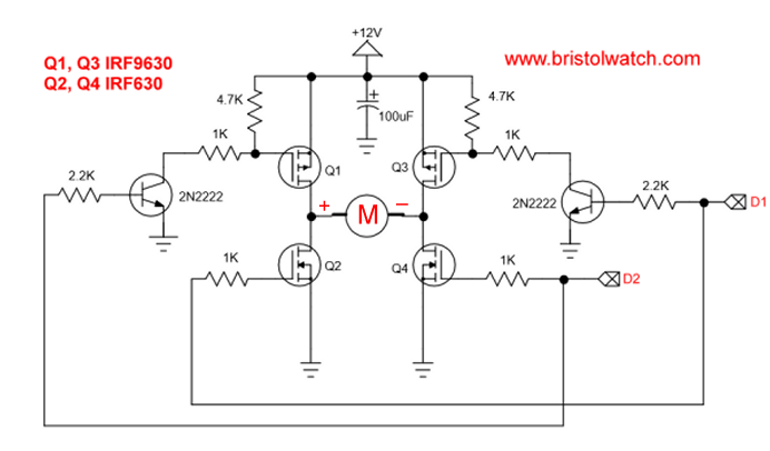
Also see H-Bridge Motor Control 2 Input Diagram.
Below assumes a connection to an Arduino microcontroller.
/*
  Forward-Reverse H-bridge control
 DP2 - Forward
 DP3 - Reverse

 DP8 - Q1 PNP PB0
 DP9 - Q2 NPN PB1
 DP10 - Q3 PNP PB2
 DP11 - Q4 NPN PB3

 Forward Q1, Q4 ON
 Reverse Q2, Q3 ON
 */

void setup() {
  pinMode(2, INPUT);
  pinMode(3, INPUT);
  digitalWrite(2, HIGH);
  digitalWrite(3, HIGH);
  // DP 8,9,10,11,13 output
  DDRB = DDRB | 0b00101111;  // 4 bytes
  // All off
  PORTB = PORTB & 0x00; // 2 bytes
}

void loop() {

  if (!digitalRead(2))   {
    PORTB = PORTB & 0x00; // off
    delay(500);
    PORTB = PORTB | 0b00101001;
  }

  if (!digitalRead(3))   {
    PORTB = PORTB & 0x00; // off
    delay(500);
    PORTB = PORTB | 0b00000110;
  }
}
See How I got into Electronics
- Arduino Port Registers Revisited
- Digispark ATtiny85 with MCP23016 GPIO Expander
- Safely Build Program a H-Bridge
- Build H-Bridge Motor Control Without Fireworks
- MOSFET H-Bridge for Arduino 2
- PICAXE Projects
- YouTube videos:
- Simple Power Distribution for Prototype Board
- Program Arduino Ports for Speed and Control
- Digispark ATtiny85 with GPIO Expansion
- Safely Program H-Bridge Motor Controller
- Build H-Bridge Motor Control without Fireworks
- MOSFET H-Bridge for Arduino 2
- Arduino Projects Revisited Revised
- Programming ADS1115 4-Channel I2C ADC with Arduino
- Arduino uses ADS1115 with TMP37 to Measure Temperature
- Connect Arduino to I2C Liquid Crystal Display
- Arduino Reads Temperature Sensor Displays Temperature on LCD Display
- Arduino with MCP4725 12-bit Digital-to-Analog Converter Demo
- Videos
- Arduino with ADS1115 4-Channel 16-bit Analog-to-Digital Converter
- Arduino with MCP4725 12-Bit DAC
- Constant Current Circuits with the LM334
- LM317 Constant Current Source Circuits
- Introduction Hall Effect Switches, Sensors, and Circuits
- Microchip PIC related videos:
- How to Use K150 PIC Programmer
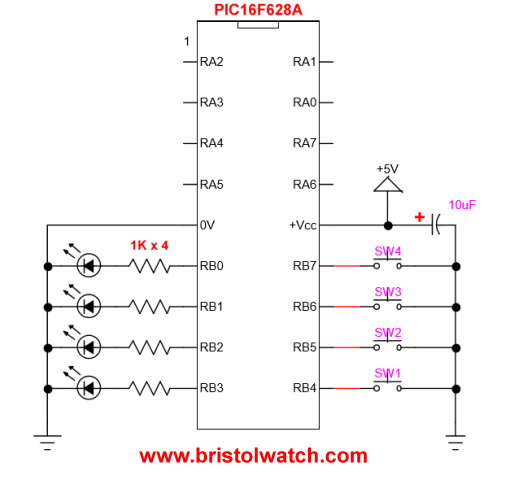
- Microchip PIC16F628A Basic H-Bridge Motor Control
- Microchip PIC16F628A Counts BCD on 8 LEDs
- PIC16F84A Operates H-Bridge Motor Control
- PIC16F84A Operates MOSFET H-Bridge
- Using Velleman K8048 PIC Development Board
- Microchip PIC16F84A H-Bridge Motor Control
- Microchip PIC16F628A Basic H-Bridge Motor Control
- PICAXE Operates H-Bridge Motor Controller
- PICAXE Micorcontroller Controls Motor Speed - Direction
- PICAXE Projects
- Arduino Port Registers Revisited
- Digispark ATtiny85 with MCP23016 GPIO Expander
- Safely Build Program a H-Bridge
- Build H-Bridge Motor Control Without Fireworks
- MOSFET H-Bridge for Arduino 2
- Web Master
- Gen. Electronics
- YouTube Channel
- Arduino Projects
- Raspberry Pi & Linux
- PIC18F2550 in C
- PIC16F628A Assembly
- PICAXE Projects
Web site Copyright Lewis Loflin, All rights reserved.
If using this material on another site, please provide a link back to my site.