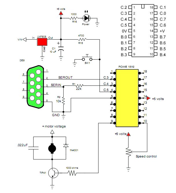
Fig. 1
PICAXE 18M2 Microcontroller PWM Motor Speed Control
The purpose of this demo is to introduce pulse-width-modulation (pwm) and the use of the PICAXE 10-bit analog to digital converter to control the speed of a DC motor. Pulse-width-modulation is used not only in say motor speed control, but in switching power supplies.
Fig. 1 is the schematic for this demo and how to connect the PICAXE 18M2 that I use. Not one can simply use a LED instead of the motor to observe the brightness in relation to the position of the potentiometer. For the speed control use a 5k or 10k pot.
In the case of the motor it can be any voltage within limits of the NPN transistor driver. The transistor is required because the micro-controller simply can't handle the power. The 1N4001 diode and 220nF cap are used to suppress electrical noise.
Fig. 2
Understanding Frequency and Duty Cycle
The three interrelated quantities of frequency, period, and duty cycle must be understood. Frequency and period are reciprocals of each other. Period = 1/frequency; so the period of 1000Hz is 1/1000 = .001 or 1 mSec. Also note 1/period = frequency.
Duty cycle refers to the relationship on/off (mark/space in the PICAXE manual) during one time period. Period also refers to a complete cycle. Fig. 2 above illustrates this relationship.
Say our frequency was 1000Hz then the period would be 1 mSec. Assuming a period of 1 mSec. for fig. 2 and an on time of of 25 percent that equates to .25 mSec. HIGH (5 volts) and .75 mSec. LOW (0 volts). The formula for duty cycle would be time HIGH (ton) divided by the period. In this case 25 percent.
The PICAXE 18M2 has only two pwm outputs at pins B.3 and B.6 and are limited to these two pins. This is implemented with hardware thus once set and running shouldn't interfere with program or vice-versa. Understanding period and duty cycle with the PICAXE is a pain in the neck. Because we can alter the frequency of the internal resonator (clock) that will completely alter our pwm output. From page 165 in their manual we get: "PWMOUT pin, period, duty cycles".
The PWM period = (period + 1) x 4 x resonator speed. At 4 mHz the resonator speed = (resonator speed for 4MHz = 1/4000000)= .25 uSec. The lower the frequency (thus longer the period) we have to divide the clock frequency. Using pwndiv4 for example will divide the 4 mHz to 1 mHz whose period is 1 uSec. It really best to use their wizard: in the compiler click PICAXE - wizards - pwmout.
Referring to above "pin" can be either B.3 or B.6 for the 18M2; period is a number from 0-255; duty cycles is a number from 0-1023. In the program below I'm using a frequency of 1000Hz and a 50 percent duty cycle. The numbers I got are based on their wizard. To stop pwmout: "pwmout pin, off" or "pwmout pin,0,0"
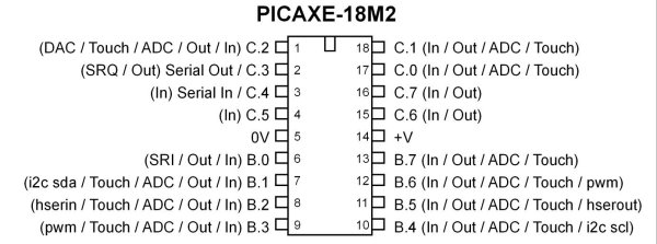
Fig. 3 PICAXE 18M2.
About the Program
The program below uses three commands. Pwmout sets up B.3 for a 1000Hz 50 percent duty cycle square wave. Readadc10 reads the position of a 5k or 10k control connected to B.4 and returns a value from 0-1023. Val must be a 16-bit "word" variable. The command "pwmduty" alters the duty cycle of the square wave from B.3 "on the fly" that is without turning it off and resetting the whole sequence. The higher the duty cycle the faster the motor should run. (Or brighter the LED.)
setfreq m4  ; All M2 parts internal k31,
; k250, k500, m1, m2, m4, m8,m16,m32

symbol speed_control = B.4
symbol val = w0 ; word (16-bit) user variable
symbol pwmPin = B.3

init:
pwmout pwmdiv4, pwmPin, 249, 500

main:
readadc10 speed_control, val
; read 10-bit ADC into variable w0
pwmduty pwmPin, val  ; set pwm duty
goto main        ; loop back to start
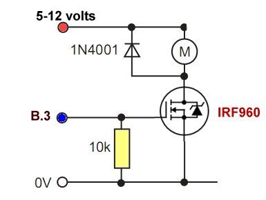
Fig. 4 uses a power MOSFET.
Picaxe Micro-controller Projects!
The PICAXE series of micro-controllers rank as the easiest and most cost effective way to use Microchip processors. I wanted an easier and less expensive way to introduce my students to the "PIC" micro-controller. Here I hope to get those starting out past poorly written literature and lack of simple working code examples.
- PICAXE Related videos Oct. 2016:
- Tutorial: Programming-Using PICAXE-18M2 Microcontroller
- How to setup PICAXE Pulse Width Modulation
- PICAXE TA8050P H-Bridge with Motor Control
- PICAXE TA8050P H-Bridge with Motor Speed Control
- PICAXE-18M2 Operates MOSFET H-Bridge
- PICAXE-18M2 Uses MCP23016 GPIO Expander
- Solar Panel Charge Controller Using PICAXE Microcontroller
- Exploring the PICAXE Micro-Controller
- Understanding Micro-Controller Input/Output Ports
- Using the 74HC165 Shift Register with the PICAXE Micro-Controller
- Connecting the 74HC595 Shift Register to PICAXE Micro-controller
- Using 7-Segment Displays with the PICAXE Micro-Controller
- Potentiometers and Analog-to-Digital Conversion with the PICAXE
- Pulse-Width Modulation Motor Speed Control and the PICAXE Micro-Controller
- Connecting the PICAXE to the DS1307 Real Time Clock
- Connecting the PICAXE to an External EEPROM (24LC08)
- Connecting a Servo to a PICAXE
- Connecting the TLC548 to the PICAXE
- Connecting the Ad5220 Digital Potentiometer to the PICAXE
See How I got into Electronics
