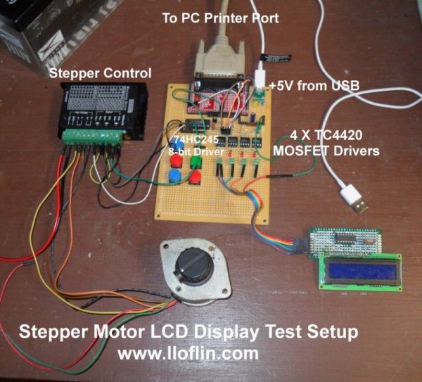
Fig. 1 Parallel demo with stepper motor and serial LCD display.
Hardware Review Connecting Parallel Ports
This a quick overview of hardware. I'll have more detailed pages on each subject.
Often known as a parallel port used from the 1970s though ~2008. It is also known as a Centronics port or printer port.
While greatly upgraded in the early 1990s for my purposes I'm interested in computers built after 2000.
They are still used in industrial settings to control CNC machines. Modules with cables are cheap on Ebay.
My purpose here is to build, test electronics including interfacing. This is real time hardware control using C under Linux.
The parallel port supplies a complete bi-directional 8-bit port, five input pins, and four control output pins. More below.
Fig. 1 is my test setup consisting of my home built interface board. One can build or buy - buy could be far easier. More on that below.
In this case I'm controlling a stepper motor and a generic 2 line by 16 character Hitachi HD44780 LCD display.
The display can be connected directly or in my case through a serial interface I designed. This was also used on Arduino and Raspberry Pi with almost similar code.
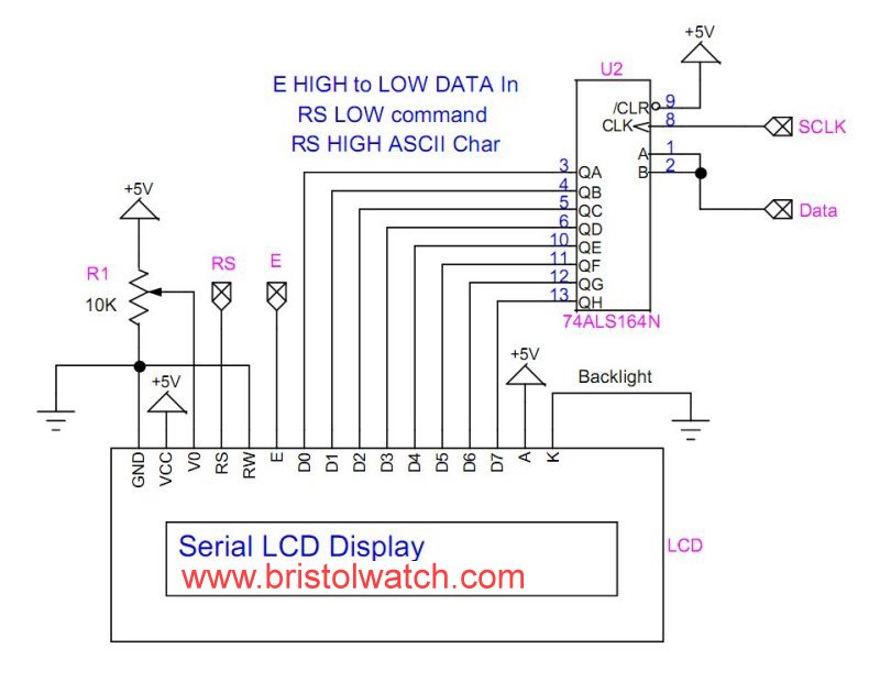
Fig. 2 SN74164 interfaced with Hitachi HD44780 LCD display.
Fig. 2 is my serial LCD board. That will be covered on another page.
See the following the same circuit used elsewhere:
- Raspberry Pi 74164 Serial Shift Register Interface Liquid Crystal Display
- Connecting Arduino to a 74C164 Shift Register
- Connect Arduino to LCD Display with 74164 Shift Register
Serial LCD Display You Tube:
74C164 shift register with Microchip PIC
74C164 shift register with Arduino
SN74164 SSR with a LCD Display and Arduino
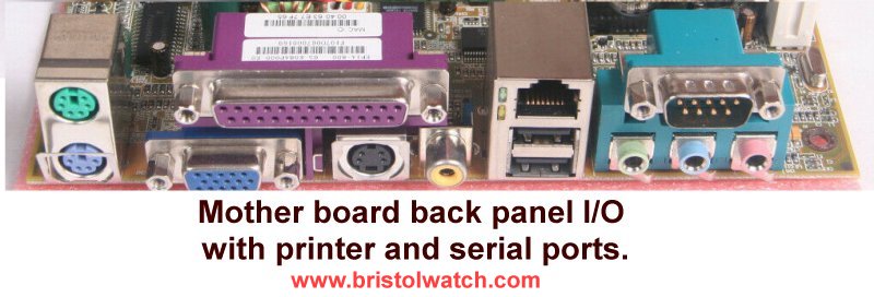
Fig. 3 Mother board back panel I/O with printer and serial ports.
This is often on the I/O panel on the back of PC motherboards. Sometimes it will be separate from the motherboard on an external bracket. It is connected to the board with a plug in header.
Today the parallel port along with serial ports have been replaced by Universal Serial Buss or USB ports.
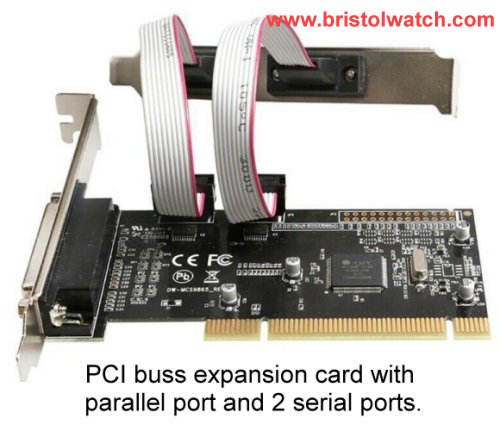
Fig. 4 PCI parallel port and 2 serial ports expansion card.
This does not refer plug in cards inserted into a PCI or PCI-E slot!
Fig. 4 is one example of a parallel port expansion card. The hardware addresses DO NOT map back to the original hardware. This requires special drivers even under Linux.
There are also USB to parallel port DB25 converters on Amazon. These also won't map back to original hardware and are useless here.
Other than the USB ports (now USB 3.0) and audio none of the other ports are used on modern PCs.
There are a lot of good computers from 2002-2010 still out there along with surplus motherboards.
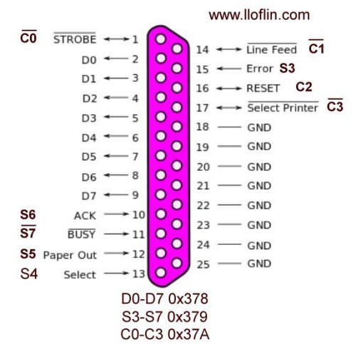
Fig. 5 Electrical connections for DB25 parallel port.
Fig. 5 illustrates the electrical connections on a parallel port. This a 25-pin female connector.
The inputs and outputs are true 5-volt logic. The output should have some type of driver circuit and the inputs should have opto-coupler isolation.
The base address I use is 0x378.
Pins 2-9 are a complete bidirectional 8-bit port labeled D0-D9 respectively. This is the DATA register at address 0x378.
Direction is determined by bit C5 in the control register at Ox37A. That bit DOES NOT appear on the connector!
Pins 10, 11, 12, 13, and 15 are inputs. This is the STATUS register. The pins are read at register address 0x379. They are pulled HIGH to 5-volts internally.
Pin 11 or register bit S7 is inverted - a HIGH input will read LOW. Bits S0-S2 are unused.
Finally the CONTROL port is at address 0x37A. These are open-collector outputs I believe.
The bits are labeled C0-C3. Bits C0, C1, and C3 are inverted - a HIGH written to the bit produces a LOW output.
This hardware must be known to program the port.
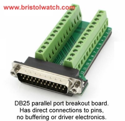
Fig. 6 Screw terminal type DB25 parallel port breakout board.
Fig. 6 is a basic parallel port breakout board from Ebay. The connections go directly to the screw terminals.
If one uses something like this be careful. One could damage the parallel port if wired incorrectly.
There are no power connections or connector cable.
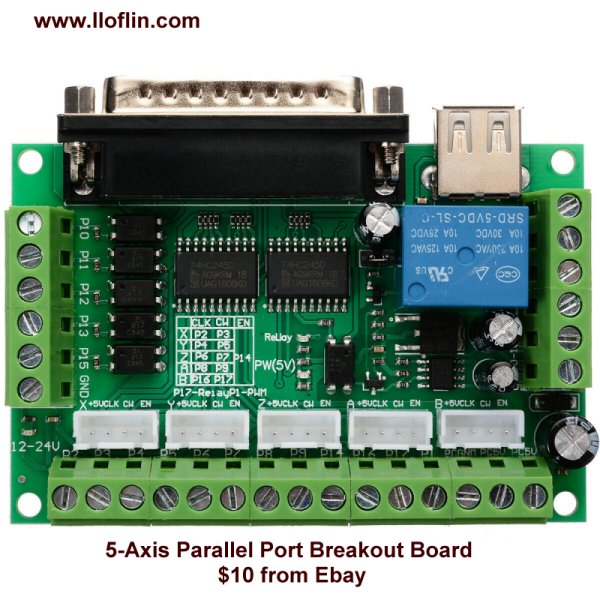
Fig. 7 Parallel port control, breakout board for CNC machines.
Fig. 7 illustrates a CNC machine parallel port control board. This is designed to connect to stepper motor controllers, switches, etc. It also includes a relay for powering the spindle motor or laser.
All connections are on screw terminal blocks. One block supplies higher voltage for the laser or spindle motor. 5-volt power for the rest of the circuits is supplied from a USB cable.
I bought one of these for $10 that included both cables.
A CNC machine is defined by www.thomasnet.com as,
The term CNC stands for 'computer numerical control', and the CNC machining definition is that it is a subtractive manufacturing process which typically employs computerized controls and machine tools to remove layers of material from a stock piece—known as the blank or work piece - and produces a custom-designed part.
This process is suitable for a wide range of materials, including metals, plastics, wood, glass, foam, and composites, and finds application in a variety of industries, such as large CNC machining and CNC machining aerospace parts. Note there is a difference between the process and the machine.
The CNC machine definition is that it represents the actual programmable machine that is capable of autonomously performing the operations of CNC machining.
Subtractive manufacturing processes, such as CNC machining, are often presented in contrast to additive manufacturing processes, such as 3D printing...
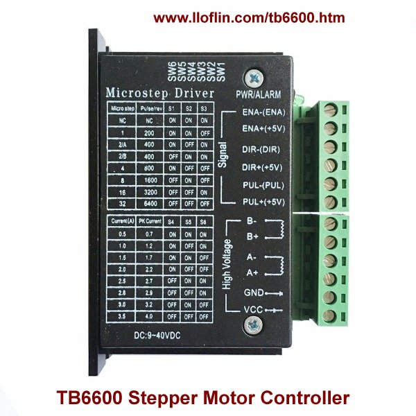
Fig. 9 TB6600 stepper motor controller electrical connections.
The parallel port control board in Fig. 8 can't directly drive motors.
A CNC machine operating through a parallel port using stepper motors requires a stepper motor controller such as the TB6600.
My home-built control board in Fig. 1 was built before I got the factory version. They used the same bi-directional DATA driver I used with a SN74LS245. I used power MOSFET drivers on the CONTROL port such as the TC4420.
- Hobby Electronics Home Page
- Donate
- Exploring Digital Computer Electronics
- Hardware
- Hardware Review Connecting PC Parallel Ports
- Operation TB6600 Stepper Controller with PC Parallel Port
- Build or Buy Parallel Port Breakout Board?
- Build Serial HD44780 LCD Display Connect to Parallel Port
- Motherboards
- Presario 1999 CM1001 Gaming Computer Salvage
- Live Test 2002 VIA EPIA-800 Mini ITX Motherboard
- Salvage, Test 2012 AAEON EMB-B75A Industrial Motherboard
- TB6600 Stepper Motor Driver with Arduino
- Use TC4420 MOSFET Driver for Simple H-Bridge Circuit
- TC4420 MOSFET Driver Various Circuits
- Introduction TC4420-TC4429 MOSFET Drivers
- TC4420 MOSFET Driver Replacement Circuits
- YouTube Videos
- Introduction TC4420-TC4429 MOSFET Drivers
- Circuit Examples for TC4420-TC4429 MOSFET Drivers
- TC4420 H-Bridge Circuit
View all of my You Tube Videos
Also visit and subscribe to My YouTube Channel
- Main Light Fast Linux Desktops with Openbox, JWM
- Test Reuse Surplus PC Power Supplies
- Add WBAR Launch Dock to Raspberry Pi
- Add MPG123 Terminal Music Player to Raspberry Pi, Linux
- Basics of Alsamixer Audio Control for Linux
- Add Solid State Hard Drive to Raspberry Pi
- Beep a PC Speaker Add Beeper to Raspberry Pi
- Using FEH Wallpaper Setter Under Linux
- Scrot Lite Weight Screen Shot Software for Linux
- Using Light Weight Beaver Text Editor
- Install Viewnior Image Viewer for Linux
- Zmixer ALSA Sound Control Tutorial
- Tutorial Xinitrc Desktop Manager Control for Linux
- Setup Raspberry Pi Using JWM Window Manager
- Off Site:
- Web Master
- Tri-Cities VA-TN
- General Science
- Hobby Electronics
- US Constitution
- Christianity 101
- Religious Themes
Web site Copyright Lewis Loflin, All rights reserved.
If using this material on another site, please provide a link back to my site.