
Difference Amplifier used with a Hall Effect Sensor.
Click for larger image.
Hall Effect Sensor Detecting AC Current
by Lewis Loflin
From a visitor:
Hello, I am having a problem reading the data from the hall effect sensor to the Arduino. The problem is not that I can't read the data but that when I turn on the device that I am attempting to read the current from my voltages will fluctuate above and below the 0-current voltage. I was wondering if their was a way that I can only get the positive voltage and the highest value. Thank you for your time.
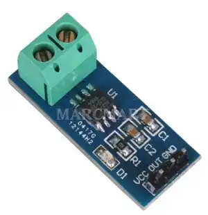
I purchased a hall effect sensor board with an ACS714T sensor and have it connected in series with the HOT wire coming from the AC outlet to my device. I would really appreciate any help. I have included a picture of the values I get and I am not changing anything just turning the device on and leaving it on. 0-current voltage is 2.5 Volts.
Ricardo
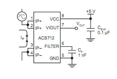
ACS712T internal diagram.
I happen to have a similar unit using an ACS712T which is nearly identical. Both are ratiometric type sensors. Hall Effect devices are made for DC, not AC as such. Devices manufactured for single polarity produce a center voltage of 2.5 volts (assuming a 5-volt unit) with no magnetic field.
Using an AC magnetic field simply produces about a 4-volt peak-to-peak sine wave (at maximum current) centered at 2.5 volts. Connecting a DC voltmeter will read only 2.5 volts, but on the AC setting one can read say 1.4 volts AC at best. None of this is very good.
It is possible to use a capacitor to block the 2.5 volts DC then rectify the AC with a diode and filter the remaining AC signal. This will leave a small voltage that's of little use for say an analog to digital converter to read.
The circuit above solves all of these problems by removing the 2.5 volts from the output and providing amplification of the DC signal. It also compensates for the voltage loss of using a diode and can be adjusted.
I chose the LM358 because it will operate at 5-volts and uses a single supply voltage.
Using the values above with no magnetic field applied to my ACS712T and its output connected to TP3 I measured 2.5 volts. At TP1 I measured 0-volts and R6 is adjusted for about 1.4 volts at TP2.
Using a permanent magnet (south pole applied to bottom of board) the output voltage peaked at 2.8 volts. (0 to 2.8 volt range.) Reverse the magnet and 0 volts output. When using AC choose values for R5 and C1 to produce a clean DC output with little AC ripple measured on an AC voltmeter. 4.7k and .1 uF should work. For a faster response time lower the value of C1.
This circuit was also tested with a UGN3503U a 3-pin device with similar results.
![]()
- Hall Sensor with Alternating Current
- Using Hall Effect Switches and Sensors
- Using Ratiometric Hall Effect Sensors
- Hall Effect Sensors with the Arduino
- YouTube videos:
- Basic Hall Effect Sensors YouTube
- Hall Effect Sensor Circuits YouTube
- Basics of Hall Effect Analog Sensors & Switches Pt. 1
- Operate, Build Hall Effect Switch Pt. 2
- Hall Effect Latches Theory and Circuits Pt. 3
- Quick navigation of this website:
- Basic Electronics Learning and Projects
- Basic Solid State Component Projects
- Arduino Microcontroller Projects
- Raspberry Pi Electronics, Programming
- Spec. sheets all PDF formate:
- UGN3013 Hall Switch (PDF file)
- TL173C 12-Volt Ratiometric Hall Sensor
- UGN3503 5-Volt Ratiometric Hall Effect Sensor
- Honeywell SS466 Hall Latch
Web site Copyright Lewis Loflin, All rights reserved.
If using this material on another site, please provide a link back to my site.