Connecting Industrial Control Transformers Examples
by Lewis Loflin
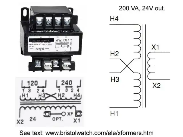
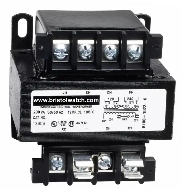
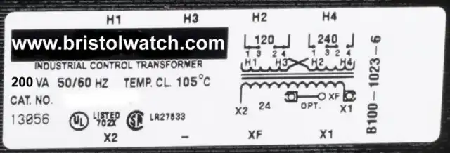
For a larger image of the above transformer see 200 VA industrial control transformer.
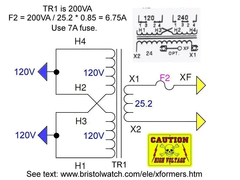
Transformers are sized by determining the total load required (in amps). Transformer capacity is rated in KVA (kilo-volt-amperes). The load voltage and load amps must be known to calculate KVA rating.
NOTE: We do not recommend loading a transformer above 80% of its KVA rating. When the KVA rating has been calculated, divide that number by 0.8 to get the minimum KVA rating needed.
Example 1: I need 24VAC at 30A; 24 * 30 = 720 VA / 1000 = 0.720 KVA; 0.720 KVA/ 0.8 = 900 VA. Use a 1 KVA transformer.
Example 2: I have a 1 KVA transformer. What are my max amps at 24V? First multiply 1 KVA * 0.8 = 800 VA; then divide 800 VA by 24V = ~33A
Ref. https:/Awww.alfatransformer.com/transformer_calculator.php
Transformer connected for 120V input.
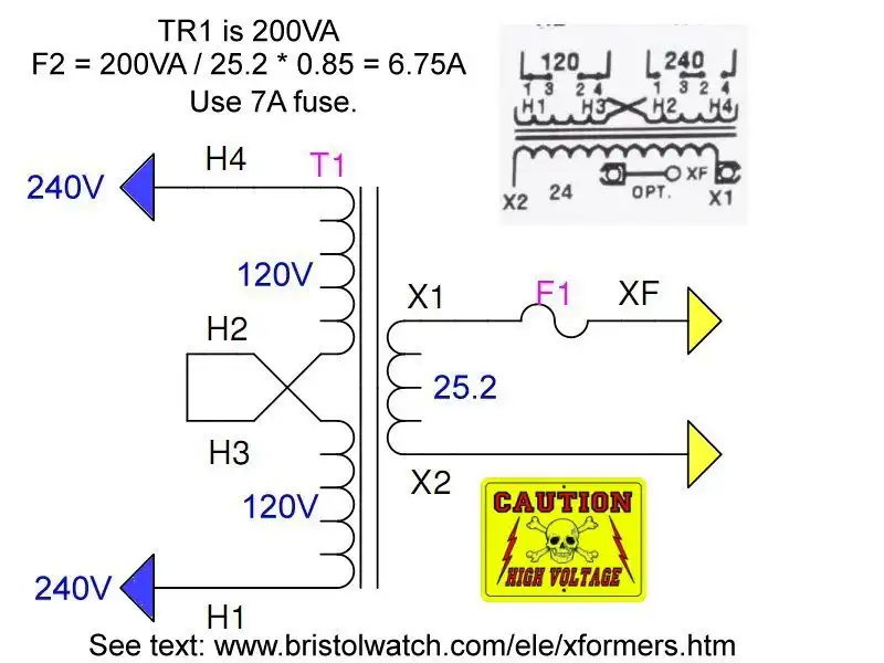
Transformer connected for 240V input.
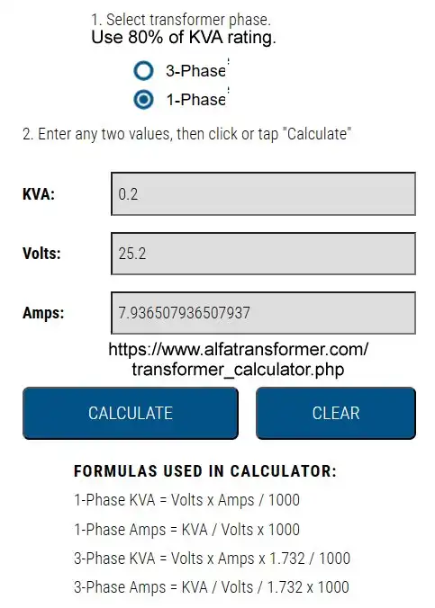
FORMULAS USED IN CALCULATOR:
1-Phase KVA = Volts x Amps / 1000
1-Phase Amps = KVA / Volts x 1000

3-Phase KVA = Volts x Amps x 1.732 / 1000
3-Phase Amps = KVA / Volts / 1.732 x 1000
"The transformer’s efficiency, in general, is in the range of 95 - 99 %. For large power transformers with very low losses, the efficiency can be as high as 99.7%."
- Basic Power Transformers
- Connecting Transformers in Series-Parallel
- Voltage Buck-Boost Transformer Connections Tutorial
- Connecting Industrial Control Transformers Examples
Misc. Topics on power transformers
A general overview of transformers and their properties.
- Autotransformer
- Magnetic Reluctance
- Magnetic Inductance
- Temperature Effect on Conductors
- Skin Effect in Conductors

Autotransformer
An autotransformer (sometimes called autoformer)is an electrical transformer with only one winding. The "auto" prefix refers to the single coil rather than any automatic mechanism. In an autotransformer a portion of the same winding acts as part of both the primary and secondary winding.
An autotransformer has only a single winding with two end terminals, plus a third at an intermediate tap point. The primary voltage is applied across two of the terminals, and the secondary voltage taken from one of these and the third terminal. The primary and secondary circuits therefore have a number of windings turns in common.
Since the volts-per-turn is the same in both windings, each develops a voltage in proportion to its number of turns. An adjustable autotransformer is made by exposing part of the winding coils and making the secondary connection through a sliding brush, giving a variable turns ratio. Such a device is often referred to as a Variac. Ref. Wiki
Back to Basic Transformers
Top of Page
Magnetic reluctance
Magnetic reluctance, or magnetic resistance, is a concept used in the analysis of magnetic circuits. It is analogous to resistance in an electrical circuit, but rather than dissipating magnetic energy it stores magnetic energy.
In likeness to the way an electric field causes an electric current to follow the path of least resistance, a magnetic field causes magnetic flux to follow the path of least magnetic reluctance. It is a scalar, extensive quantity, akin to electrical resistance.
Magnetic flux always forms a closed loop, but the path of the loop depends on the reluctance of the surrounding materials. It is concentrated around the path of least reluctance.
Air and vacuum have high reluctance, while easily magnetized materials such as soft iron have low reluctance. The concentration of flux in low-reluctance materials forms strong temporary magnetic poles and causes mechanical forces that tend to move the materials towards regions of higher flux so it is always an attractive force(pull).
The inverse of reluctance is called permanence, measure of the ability of a magnetic circuit to conduct magnetic flux.
Back to Basic Transformers
Top of Page
Electromagnetic Induction
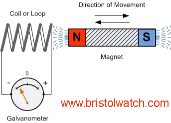
Electromagnetic induction is the complementary phenomenon to electromagnetism. Instead of producing a magnetic field from electricity, we produce electricity from a magnetic field.
There is one important difference, though: whereas electromagnetism produces a steady magnetic field from a steady electric current, electromagnetic induction requires motion between the magnet and the coil to produce a voltage.
Connect the multimeter to the coil, and set it to the most sensitive DC voltage range available. Move the magnet slowly to and from one end of the coil, noting the polarity and magnitude of the induced voltage.
Experiment with moving the magnet, and discover for yourself what factor(s) determine the amount of voltage induced. Try the other end of the coil and compare results. (Polarity should reverse.) Try the other end of the permanent magnet and compare.
If using an analog multimeter, be sure to use long jumper wires and locate the meter far away from the coil, as the magnetic field from the permanent magnet may affect the meter's operation and produce false readings. Digital meters are unaffected by magnetic fields.
Ref. http://www.allaboutcircuits.com/vol_6/chpt_2/10.html
Back to Basic Transformers
Top of Page
Temperature versus Resistance
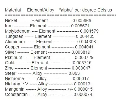
You might have noticed on the table for specific resistances that all figures were specified at a temperature of 20 degrees Celsius. If you suspected that this meant specific resistance of a material may change with temperature, you were right!
The "alpha" (a) constant is known as the temperature coefficient of resistance, and symbolizes the resistance change factor per degree of temperature change. Just as all materials have a certain specific resistance (at 20 degrees C), they also change resistance according to temperature by certain amounts.
For pure metals, this coefficient is a positive number, meaning that resistance increases with increasing temperature. For the elements carbon, silicon, and germanium, this coefficient is a negative number, meaning that resistance decreases with increasing temperature.
For some metal alloys, the temperature coefficient of resistance is very close to zero, meaning that the resistance hardly changes at all with variations in temperature (a good property if you want to build a precision resistor out of metal wire!). The following table gives the temperature coefficients of resistance for several common metals, both pure and alloy:
REVIEW:
Most conductive materials change specific resistance with changes in temperature. This is why figures of specific resistance are always specified at a standard temperature (usually 20 degrees or 25 degrees Celsius).
The resistance-change factor per degree Celsius of temperature change is called the temperature coefficient of resistance. This factor is represented by the Greek lower-case letter "alpha" (a).
A positive coefficient for a material means that its resistance increases with an increase in temperature. Pure metals typically have positive temperature coefficients of resistance. Coefficients approaching zero can be obtained by alloying certain metals.
A negative coefficient for a material means that its resistance decreases with an increase in temperature. Semiconductor materials (carbon, silicon, germanium) typically have negative temperature coefficients of resistance.
Ref. http://www.allaboutcircuits.com/vol_1/chpt_12/6.html
Back to Basic Transformers
Top of Page
Question - Would Temperature Effect the Amount of Current Traveling Through A Copper Wire?
Yes, very much. There is even a name for a condition that when the copper wire (or any material) is so cold that there is no resistance to electrical flow. That condition is called superconductivity. The temperature that copper doesn't have any resistance to flow is around -410 F (very, very cold).
The general rule is "the higher in temperature the wire is, the higher the resistance to electrical flow. It would be nice to have no resistance to electrical flow, but we can't always have copper at very cold temperatures.
That's why researchers are working on superconductors that have no resistance to current flow at higher temperatures. Currently most superconductors are ceramics that act as superconducting at around -320 F.
That's still cold, but that is also the temperature of liquid nitrogen, so if you keep the superconductor in a bath of liquid nitrogen, it will stay superconducting.
Back to Basic Transformers
Top of Page
Skin effect
Skin effect is the tendency of an alternating electric current (AC) to distribute itself within a conductor so that the current density near the surface of the conductor is greater than that at its core. That is, the electric current tends to flow at the "skin" of the conductor, at an average depth called the skin depth.
The skin effect causes the effective resistance of the conductor to increase with the frequency of the current because much of the conductor carries little current. Skin effect is due to eddy currents set up by the AC current. At 60 Hz in copper, skin depth is about 8.5 mm. At high frequencies skin depth is much smaller.
Methods to minimize skin effect include using specially woven wire and using hollow pipe-shaped conductors. Another method is the use of wide thin conductors (ribbon) instead of round wire at high currents.
![]()
- Quick navigation of this website:
- You Tube Channel
- Basic Electronics Learning and Projects
- Basic Solid State Component Projects
- Arduino Microcontroller Projects
- Raspberry Pi Electronics, Programming
- Quick navigation of this website:
- Basic Electronics Learning and Projects
- H-Bridge Motor Controls
- Transistor Switching Circuits
- Power Supplies Projects
- Switching Power Supply Projects
- Battery Chargers with Arduino Controller
- Opto-Coupler, SCR, and Triac Circuits AC Power Control
- Zero-Crossing Detectors for AC Power Control with Arduino
- DIACs, SIDACs, and Unijunction Transistors Switching Circuits
- Xenon Flash Tube Circuits - High Voltage!
- Hall Sensors Circuits and Sensors for Magnetic Detection
- Comparator Circuit Examples
- Constant Current and Current Limiter Circuits
- Photo Diode Detector Circuits
- Digital Circuits and Projects
- Stepper Motor Operation and Control
- Crystal Radio, Odds and Ends Circuits
- Geiger Counters and Science Topics
- Popular Webpages & Corresponding Videos
- YouTube Videos List
- Off Site:
- Bristolblog an Alternative News Skeptic Site
- Web Master
- Tri-Cities VA-TN
- General Science
- US Constitution
- Christianity 101
- Religious Themes
Web site Copyright Lewis Loflin, All rights reserved.
If using this material on another site, please provide a link back to my site.