Connecting Transformers in Series-Parallel
by Lewis Loflin
A transformer is an electrical device used for either electrical power conversion or electrical isolation for safety, often both.
Here I'm concerned only with small single-phase power transformers, how to connect them in series-parallel, and basic power supply construction.
This is a lab project for a community college. This uses voltages that can lead to electrical shock so this must be done under proper conditions.
Transformers operate by magnetic induction. Their power ratings for this reason are rated as kilo-volt amperes (KVA) or volt-amperes (VA). This is reactive power.
Transformers work only with alternating current (AC) or pulsating DC. This is required to produce a pulsating magnetic field.
Lab 1: open circuit voltage
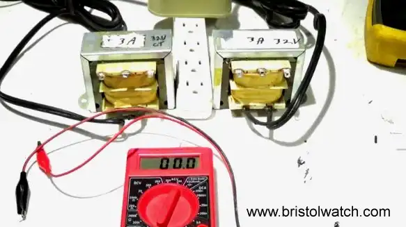
For this series of labs I'll be using the two transformers in Fig. 1. They are salvage from scrap equipment and are identical.
I could not find the part numbers so I ran series of tests. Both measured an open-circuit voltage of ~32 volts AC.
The reality is open-circuit voltages are often higher, sometimes much higher, than voltage under load. Under load is our real voltage.
I connected a 20 Ohm load across the transformer terminals drawing ~1.6 amps. This produced a voltage drop of barely 1 volt. This is good.
The secondary wire seemed to 20 Gauge, the primary wire 22 Gauge. 20 Gauge can easily carry 3 amps while 22 Gauge can easily carry 1 amp.
Both were single strand solid core wire. So I rated the secondary at 3 amps at 32 volts or 96 VA.
To quote https://eepower.com "The efficiencies of power transformers normally vary from 97 to 99 percent." Low quality consumer electronics transformers are less than this.
Assuming 100% efficiency (no transformer is 100% efficient) that means the primary must also deliver 96 VA, more likely 100 VA to make up for losses.
100 VA / 120 volts = ~834mA. A 1 amp fuse should work.
Note both transformers being electrically identical also have center-tapped connections. Connecting one side of a voltmeter to the center-tap. each outer terminal reads ~16V.
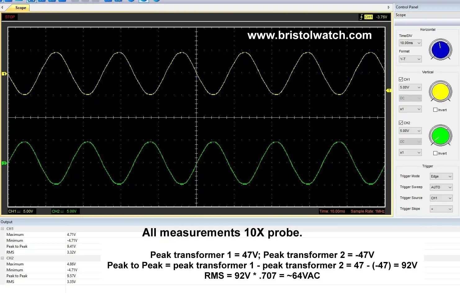
If one viewed this on a 2-channel oscilloscope with the center-tap common the two outer terminals are 180 degrees out of phase.
See graphic Out of Phase Waveforms. Note when channel 1 is peak positive channel 2 is peak negative.
This is the same phase relationship one would find for transformer winding in series and 180 degrees out of phase - voltages add.
Remember voltage is the potential DIFFERENCE between 2 points. More below.
Knowing the phase relationships is key to connecting transformers in serial and/or parallel.
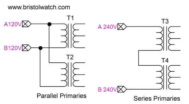
Fig 2
Because my 2 transformers came with 120 volt power plugs when plugged into a wall outlet will be parallel inputs as shown on the left in Fig. 2.
If I had these same 2 transformers on a 240 volt system I would need to connect the two 120 volt primaries in series as shown on the right of Fig. 2.
It is important to note the direction of primary windings relates directly to the phase relationships of the secondaries. This is no problem with a single transformer, but can be a nightmare if the windings get reversed in 3-phase systems.
From here on a assume parallel power inputs. Now let's turn to serial and parallel connections of the transformer secondaries.
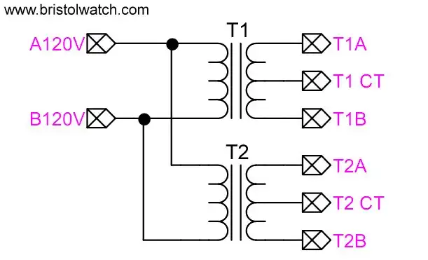
Fig. 3
Phase Relationships for Serial-Parallel Transformer connections
Fig. 3 illustrates my two transformers with parallel connected inputs to 120VAC. The outputs are labeled as shown.
The phase relationships of the output connections in regards to each other are unknown. Phase is related to the DIRECTION of the winding of the wire.
If I remember correctly the phase of the secondary winding is always 180 degrees out of phase with the primary winding. This is a property of magnetic induction.
There is no way to know the phase unless one has the manufacturer's spec sheet and the unit is marked.
I could use an oscilloscope but a voltmeter works just as well for simple series/parallel connections.
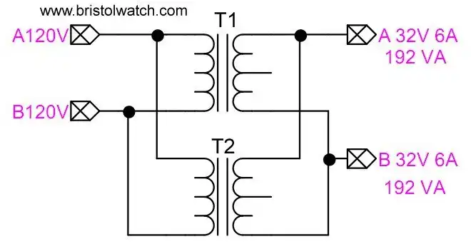
Fig. 4
Transformer Outputs in Parallel
Fig. 4 illustrates the output connections from my two transformers in parallel. Why would I do this? Again the transformers are rated 3 amps at 32 volts.
This would double the output current to 6 amps but the voltage remains 32VAC.
Note: the output voltage of the two transformers must be the same! Otherwise the transformers can be damaged.
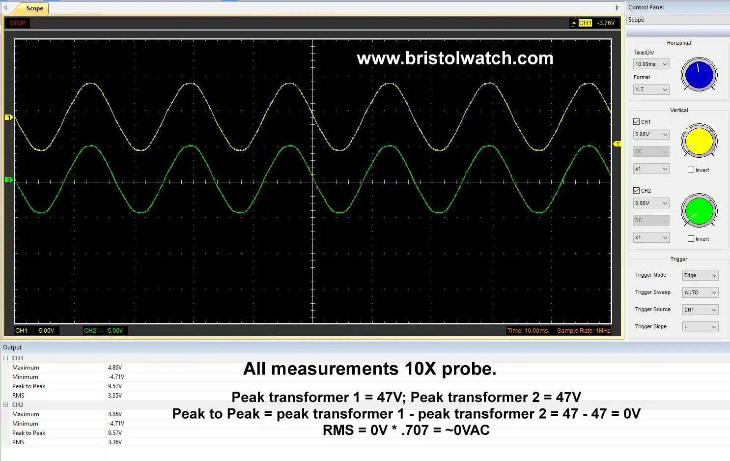
Thus the phase relationship of the two transformers must also be in phase. This is illustrated in the graphic in_phase1.jpg shows positive and negative waveforms on channels 1 and 2 are identical, going positive and negative at the time.
Note again the terminal connections in Fig. 3 and have an AC voltmeter handy.
Connect terminals T1B to T2A or T2B. Measure between the two open terminals. If zero volts (a few milli-volts is OK) then connect the two open terminal together and you are done.
If reading 64VAC reverse and say T2A is connected, change the T2A connection to T2B and check again.
To sum this up transformer outputs when connected in parallel the AC voltages MUST be in phase and the same voltage output. The currents will add.
If using a 1A fuse on each transformer should be changed to 2A for both.
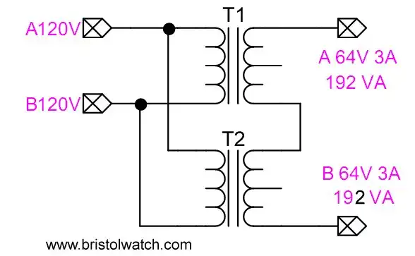
Fig. 5
Transformer Outputs in Series
Note again the terminal connections in Fig. 3 and have an AC voltmeter handy.
Connect terminals T1B to T2A or T2B. Measure between the two open terminals. If measuring 64VAC you are done use the two open terminals.
If reading zero volts and say T2A is connected to T1B, change the connection to T2B to T1Band measure again.
The two transformer secondaries must be 180 degrees out of phase and the voltages add, but the total current (3A) stays the same.
See graphic Out of Phase Waveforms. Note when channel 1 is peak positive channel 2 is peak negative.
One can connect transformers with differing voltage and current in series but interesting things can happen. Here are some examples.
Transformer T1 is rated 16V at 1A. Transformer T2 is rated 32V at 2A.
If connected in series and voltages are in phase they subtract. The result would be 16V at 1A. The current is limited the smallest current transformer due to wire gauge.
If connected in series and voltages are out of phase they add. The result is 48V at 1A. I'm still limited by the smaller current rating due to smaller wire in the 1A transformer.
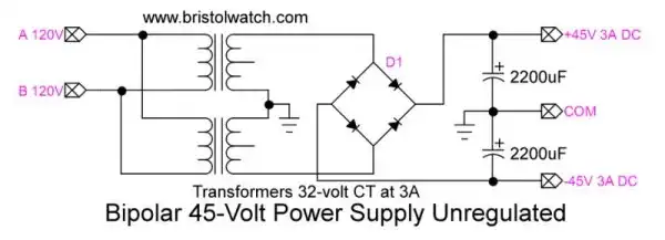
Fig. 6 Bipolar power supply using two series connected transformers.
See Youtube video How to Connect Series-Parallel Transformers.
See my other two pages on transformer basics:
- Basic Power Transformers
- Connecting Transformers in Series-Parallel
- Voltage Buck-Boost Transformer Connections Tutorial
- Connecting Industrial Control Transformers Examples
![]()
- Quick navigation of this website:
- You Tube Channel
- Basic Electronics Learning and Projects
- Homepage Lewis Loflin
- Follow on X
- Skeptic Site
- Religion 1
- Religion 2
- Coils for Highly Selective Crystal Radio
- Neon (NE-2) Circuits You Can Build
- Understanding Xenon Flashtubes and Circuits
- Hall Effect Magnetic Switches and Sensors
- Transistor-Zener Diode Regulator Circuits
- Build an Adjustable 0-34 volt power supply with the LM317
- Simple 2 Transistor LED Flasher Circuit
- LM2575 Simple Switching Voltage Regulators
- LM317 Constant Current Source for Lighting LEDs
- IGBT Based High Voltage H-Bridge DC Motor Control
- Arduino Controlled IR2110 Based H-Bridge HV Motor Control
- Understanding Unijunction Transistors Theory Operation
- Arduino Measures Current from Constant Current Source
- Constant Current Source Theory Testing
- Review Ohm's Law for Trouble-Shooting CCS Circuits
- Arduino Power Magnetic Driver Board for Stepper Motors
- Arduino Controlled Power Constant Current Source
- Theory and Operation of Capacitors
Related video to above:
- Measure Current from Constant Current Source with Arduino
- Constant Current Source Multimeter Trouble Shooting
- Ohm's Law Review for Constant Current Source
- Arduino Unipolar Stepper Motor Driver Board with Arduino Code
- Arduino Controlled Constant Current Source
- LM317 Adjustable Current Boost Power Supply
- Constant Current Circuits LM334, LM317
- Build LM317 0-34 Volt Power Supply
- LM334 Constant Current Source with Resistive Sensors
- LM317 High Power Constant Current Source Circuit
- LM317 Constant Current Source Circuits
- Test SCRs and Triacs
- Basic MOSFET Transistor Test Circuits
- High Voltage MOSFET Switching Circuits
- 3 Amp LM741 Op-Amp Constant Current Source
- Current Limiter Testing of Zener Diodes
- Current Limiter for Opto-Coupler Inputs
- LM317 CCS for Light Emitting Diodes
Web site Copyright Lewis Loflin, All rights reserved.
If using this material on another site, please provide a link back to my site.