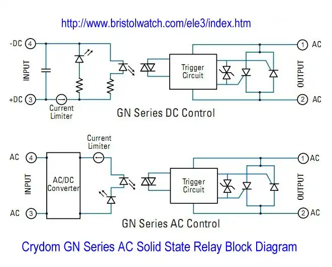
Fig. 1
Current Limiter Circuits for Opto-Coupler LEDs
by Lewis Loflin
See Exploring Solid State Relays and Control Circuits
I started of looking into circuits based on Crydom high-current GN series solid state relays. Notable is the use of constant current sources (current limiters) for LED inputs on the associated opto-couplers.
Here I'll look at current limiter circuits using the popular LM334 and the LM317. The idea is construct circuits without the use of exotic custom parts.
For the opto-couplers in themselves see Comparing Photo Triac, Photo SCR Opto-Couplers.
For reference to the rest of the circuits presented here see:
- Constant Current Circuits with the LM334
- LM334 CCS Circuits with Thermistors, Photocells
- LM317 Constant Current Source Circuits
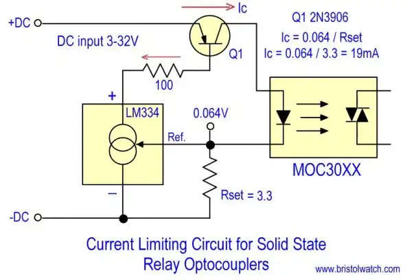
Fig. 2
LM334 used as a current limiter for optocoupler LED input. The formula is simple with the Ref. at 0.064V / Rset.
In this case 0.o64 divided by 3.3 Ohms = ~19mA. 19mA will operate any opto-coupler I have. If more current is needed replace Rset with 2.7 Ohms for 24mA or even 1 Ohm for 64mA. Most LED input are limited to 60mA.
The voltage input range is 3-32 volts DC.
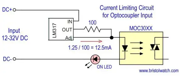
Fig. 3
Fig. 3 illustrates an LM317 used as a current limiter for opto-coupler LED input for solid state relay. While simpler than Fig. 2 but the input voltage range won't go below 7-volts. This is due to the LM317.
If there is any question of enough current drive for the LED change the 100 Ohm resistor to 47 Ohms.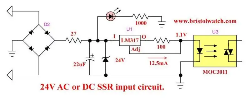
Fig. 4
Fig 4 is a 24-volt AC-DC opto-coupler input circuit using an LM317. If DC only input is required leave out the diode bridge, Zener diode, 22uF cap, and 27 Ohm resistor.
- Exploring Solid State Relays and Control Circuits
- Comparing Photo Triac, Photo SCR Opto-Couplers
- Light Activated SCR Based Optocouplers Circuit Examples
- Silicon Controlled Rectifier Review and Circuits
- Silicon Controlled Rectifiers Connected as Power Triacs
- Insulated Gate Bipolar Transistor IGBT Circuits
- Current Limiter Circuits for Opto-Coupler LEDs
- VOM1271 Photovoltaic MOSFET Driver Circuits
- Current Limiter Allows Safe Testing of Zener Diodes, LEDs
- 3 Amp LM741 Op-Amp Constant Current Source
- Bidirectional Solid State Relay Circuits
- Simple Solid State Relay for Low Power LED 120V Lamps
- Build High Power MOSFET Directional Switch Relay
- Optical Isolation of H-Bridge Motor Controls
- All NPN Transistor H-Bridge Motor Control
- Basic Transistor Driver Circuits for Micro-Controllers
- ULN2003A Darlington Transistor Array with Circuit Examples
- Tutorial Using TIP120 and TIP125 Power Darlington Transistors
- Driving 2N3055-MJ2955 Power Transistors with Darlington Transistors
- Understanding Bipolar Transistor Switches
- N-Channel Power MOSFET Switching Tutorial
- P-Channel Power MOSFET Switch Tutorial
- Build a Transistor H-Bridge Motor Control
- H-Bridge Motor Control with Power MOSFETS
- More Power MOSFET H-Bridge Circuit Examples
- Build a High Power Transistor H-Bridge Motor Control
- H-Bridge Motor Control with Power MOSFETS Updated
- Opto-Isolated Transistor Drivers for Micro-Controllers
- Comparator Theory Circuits Tutorial
- Constant Current Circuits with the LM334
- LM334 CCS Circuits with Thermistors, Photocells
- LM317 Constant Current Source Circuits
- TA8050P H-Bridge Motor Control
- All NPN Transistor H-Bridge Motor Control
- Basic Triacs and SCRs
- Comparator Hysteresis and Schmitt Triggers
- Comparator Theory Circuits Tutorial
- Photodiode Circuits Operation and Uses
- Optocoupler MOSFET DC Relays Using Photovoltaic drivers
- Connecting Crydom MOSFET Solid State Relays
- Photodiode Op-Amp Circuits Tutorial
- Optocoupler Input Circuits for PLC
- H11L1, 6N137A, FED8183, TLP2662 Digital Output Optocouplers
- Optical Isolation of H-Bridge Motor Controls
- All NPN Transistor H-Bridge Motor Control
© Copyright 2019 Lewis Loflin E-Mail