Fig. 1
Photodiode Circuits Operation and Uses
by Lewis Loflin
Photodiodes have many varied uses today both as light sensors and used for driving power MOSFETs when used in photovoltaic opto-couplers. This series of webpages will explore all of this.
Here we start with basic operation of a photodiode, its construction, and improving switching speed. In other pages we will explore both commercial devices and how to build your own circuits. What follows is a listing of related pages.
This is oriented towards the hobbyist or junior engineer in a community college. We are interested in practical uses more than just theory. Driving AC-DC motors or light level detection are just a few applications.
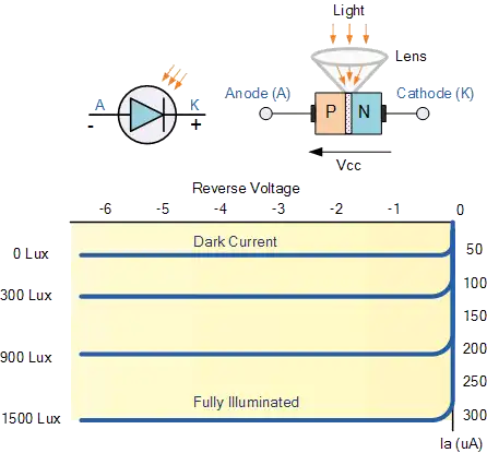
Fig. 1 illustrates the current and voltage relationship of a photodiode used as a light sensor. A photodiode is simply a PN silicon diode where light will generate a current proportional to light intensity on the PN junction depletion region. The photodiode is reversed biased where the Cathode goes to a positive voltage and th Anode goes to the negative side of the supply.
The graph shows the current to light relationship. Even in complete darkness a small current called dark current will flow. This property of often used to measure light intensity.
For more on this see Photodiode Op-Amp Circuits Tutorial.
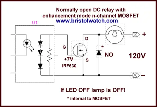
Fig. 2
Fig. 2 illustrates using an ohm meter on a diode check setting. A photodiode will check much the same as any other silicon diode with a forward biased voltage drop of about ~0.5V.
Fig. 3
Fig. 3 shows how a photodiode can act as a mini solar cell that outputs a voltage in bright light. This property is used in photovoltaic opto-couplers to switch ON-OFF power MOSFETs which are voltage operated devices. This involves connecting several PN junctions in series to generate several volts when a LED emitter is switched on.
For more on this see MOSFET DC Relays Using Photovoltaic drivers
Fig. 4
Fig. 4 shows the physical construction on the silicon wafer. We have a thin anode (P-type) that allows light into the depletion region while the bulk of the material is N-type.
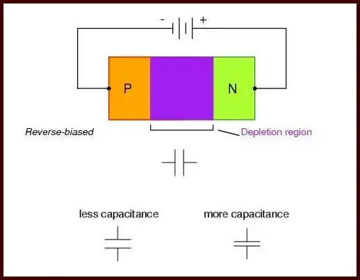
Fig. 5
Refer to Fig. 5. When a PN junction is reversed biased it forms a small capacitor. The depletion region becomes an insulator and acts as a capacitor dielectric between two conductors. The higher the reverse bias the wider the depletion region and less capacitance - the region varies based on the reverse bias voltage. Note: don't exceed the breakdown voltage!
Capacitance limits the switching frequency and distorts high speed waveforms so reducing capacitance is vital to increase high frequency response.
Fig. 6
Fig. 6 shows the construction of a PIN photodiode. The big difference is the introduction of an intrinsic region where the silicon is lightly doped or undoped totally - just a piece of silicon. This helps create a larger spacing between the outside conductors reducing capacitance.
Fig. 7
Fig. 7 shows two example photodiodes. The large surface area increases sensitivity, but will introduce higher capacitance sacrificing switching speed. Choosing between frequency response and sensitivity is a trade off depending on application.
Fig. 8
Fig. 8 shows a photodiode test circuit I constructed. D1 was a MRD105 type that is reversed biased. When the UV LED is turned on a small current Id is amplified by Q1 a NPN transistor to turn on a LED. What I found out from using several LEDs of differing colors was D1 was color sensitive in particular to blue and UV. This property is useful in digital cameras, etc.
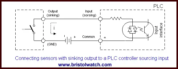
Fig. 9
Fig. 9 illustrates the internal construction of 6N135 and 6N136 opto-couplers. The circuit is identical to my test circuit in using a reverse bias on the diode and a NPN transistor to boost current - it's likely using a PIN photodiode, but wasn't specific in the specification sheet.
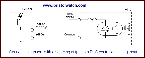
Fig. 10
Fig. 10 shows a typical test connection for the 6N135 and 6N136. The diode can be connected to say 12-volts while RL would be connected to a 5-volts supply. Doing that will improve switching speed and still enable one to connect the output to a microcontroller. Leave out CL when using this for a real application.
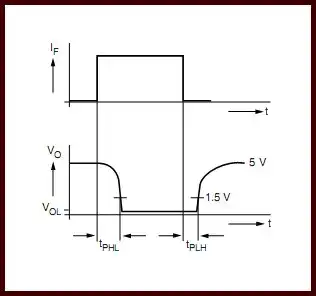
Fig. 11
Fig. 11 illustrated the effect of capacitance on a waveform and why it is undesirable. These type opto-couplers would be used for interfacing sensors such as in fuel injections system, high speed robotics, etc.
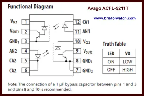
Fig. 12
Fig. 12 AVAGO AFCL-5211T internal diagram with two complete emitter-detector pairs.
The reason we use opto-couplers in general is to interface differing voltage levels, voltage isolation between high voltage sensors and low-voltage micro-controllers, and noise immunity.
I hope this introduction was useful. Feel free to do more research into these devices.
- Quick navigation of this website:
- Basic Electronics Learning and Projects
- Basic Solid State Component Projects
- Arduino Microcontroller Projects
- Raspberry Pi Electronics, Programming
- Comparator Theory Circuits Tutorial
- Zero-Crossing Detectors Circuits and Applications
- Improved AC Zero Crossing Detectors for Arduino
- Photodiode Circuits Operation and Uses
- Photodiode Op-Amp Circuits Tutorial
- Issues on Connecting MOSFETs in Parallel
- MOSFET DC Relays Using Photovoltaic drivers
- Optocoupler Input Circuits for PLC
- All NPN Transistor H-Bridge Motor Control
- Photo Voltaic Tutorial MOSFET Output Solid State Relays
- Optical Isolation of H-Bridge Motor Controls
- Design 10-Amp 2N3055 Based Power Switch
- TA8050P H-Bridge Motor Control
- Connecting Crydom MOSFET Solid State Relays
- H11L1, 6N137A, FED8183, TLP2662 Digital Output Optocouplers
- Arduino
- Arduino PWM to Analog Conversion
- Arduino Analog Digital Conversion Voltmeter
- Better Arduino Rotary Encoder Sensor
- Simple 3-Wire MAX6675 Thermocouple ADC Arduino Interface
- Hall Effect Magnetic Switches and Sensors
- Transistor-Zener Diode Regulator Circuits
- Build an Adjustable 0-34 volt power supply with the LM317
- Coils for Highly Selective Crystal Radio
- Neon (NE-2) Circuits You Can Build
- Understanding Xenon Flashtubes and Circuits
- LM2575 Simple Switching Voltage Regulators
- Simple 2 Transistor LED Flasher Circuit
- Generating High Voltage with an Inductor
Web site Copyright Lewis Loflin, All rights reserved.
If using this material on another site, please provide a link back to my site.