Fig. 1
Optical Isolation H-Bridge Motor Controls
What's new?
For November-December 2014 this website decided to focus on practical transistor theory both bipolar and MOSFET. This included a series of 10 You Tube videos three on constant current source circuits, one on the PIC12F683 micro-controller, most of the rest on transistor circuits. This included several new pages and extensive updates and new graphics for several others.
The particular interest of the reader seems to be motor control circuits for robotics and 3D printers. This page and the associated video demonstrate the following:
The use of opt-couplers for electrical isolation between a micro-controller and higher-voltage motor drive circuits can prevent a lot of problems.
The use again of opto-isolation with the use of series speed control circuits placed in either the ground side of an H-bridge or in Vcc. This video used the ground side while the page on the TA8050P H-bridge control used the Vcc side.
While the video used a PIC12F683 which happened to be what I was doing a separate video and webpage on, the very same circuits work identical with Arduino or other micro-controller.
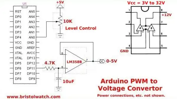
Fig. 1 show the PIC12F683 connection to the H-bridge module. The grounds are separate in order to insert the speed control circuits in the ground side of the motor power supply. I could tie the two power supply grounds together and insert the PWM control in the +Vcc side of the H-bridge.
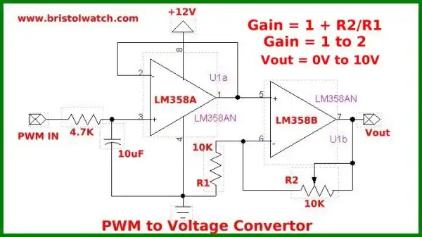
Fig. 2
Fig. 2 shows the schematic for this particular MOSFET H-bridge. The digital ground from the micro-controller is separate from the motor power ground.
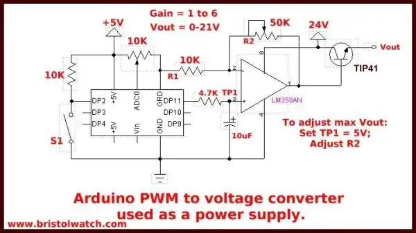
Fig. 3
Fig. 3 shows the speed control circuit. The speed is controlled by pulse-width modulation.
See:
Opto-Isolated Transistor Drivers for Micro-Controllers
Pulse-Width Modulation Tutorial
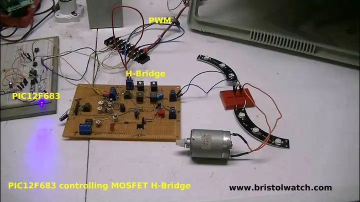
Fig. 4
- Quick navigation of this website:
- Basic Electronics Learning and Projects
- Basic Solid State Component Projects
- Arduino Microcontroller Projects
- Raspberry Pi Electronics, Programming
- Comparator Theory Circuits Tutorial
- Zero-Crossing Detectors Circuits and Applications
- Improved AC Zero Crossing Detectors for Arduino
- Photodiode Circuits Operation and Uses
- Photodiode Op-Amp Circuits Tutorial
- Issues on Connecting MOSFETs in Parallel
- MOSFET DC Relays Using Photovoltaic drivers
- Optocoupler Input Circuits for PLC
- All NPN Transistor H-Bridge Motor Control
- Photo Voltaic Tutorial MOSFET Output Solid State Relays
- Optical Isolation of H-Bridge Motor Controls
- Design 10-Amp 2N3055 Based Power Switch
- TA8050P H-Bridge Motor Control
- Connecting Crydom MOSFET Solid State Relays
- H11L1, 6N137A, FED8183, TLP2662 Digital Output Optocouplers
- Arduino
- Arduino PWM to Analog Conversion
- Arduino Analog Digital Conversion Voltmeter
- Better Arduino Rotary Encoder Sensor
- Simple 3-Wire MAX6675 Thermocouple ADC Arduino Interface
- Hall Effect Magnetic Switches and Sensors
- Transistor-Zener Diode Regulator Circuits
- Build an Adjustable 0-34 volt power supply with the LM317
- Coils for Highly Selective Crystal Radio
- Neon (NE-2) Circuits You Can Build
- Understanding Xenon Flashtubes and Circuits
- LM2575 Simple Switching Voltage Regulators
- Simple 2 Transistor LED Flasher Circuit
- Generating High Voltage with an Inductor
Web site Copyright Lewis Loflin, All rights reserved.
If using this material on another site, please provide a link back to my site.