Opto-Isolated Transistor Drivers Microcontroller Interfacing
by Lewis Loflin
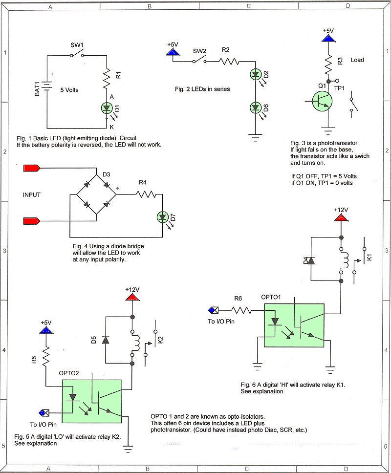
In part 1 we looked at a number of bipolar transistor and MOSFET driver circuits. They had a flaw of having to be electrically connected to low voltage digital circuits.
With opto-isolators we can sever this connection including the use of higher-voltage power supplies totally isolated from the low-voltage digital circuits. In fact we can even change the polarity of the higher voltage supplies without regard to the digital circuit common negative grounds if needed.
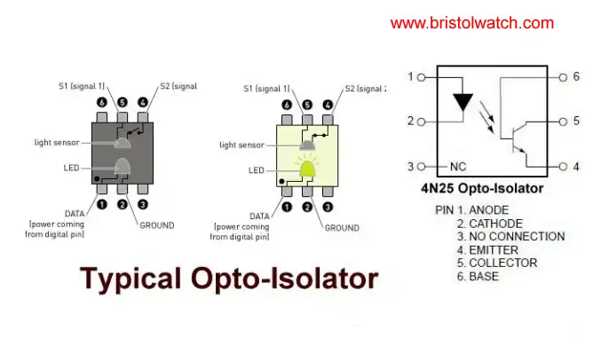
Q1 is a NPN bipolar photo transistor and both the LED and transistor are often one physical device. Again an important note is the output has no electrical connection to the input and can isolate several thousand volts. Also see More sample circuits.
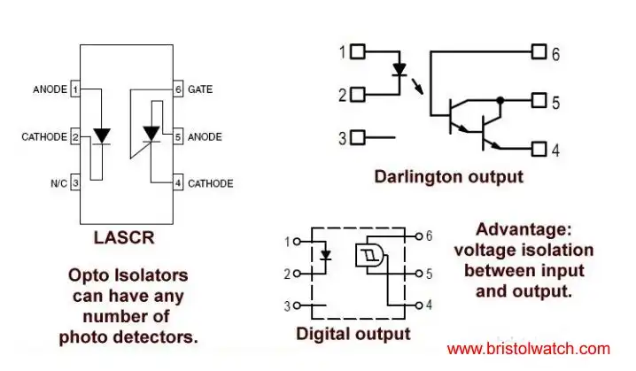
While most opto-isolators use a LED infrared emitter the detector can include photo SCRs, Darlington transistors, and even digital circuits.
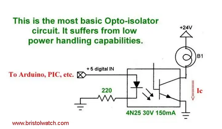
The output transistor of a 4N25 is still a low power device, so we must use it to drive higher power components for greater loads. This is usually higher power bi-polar transistors or power MOSFETs.
What can we use opto-couplers for?
The 4N25, 4N26, 4N27 and 4N28 devices consist of a gallium arsenide infrared emitting diode optically coupled to a monolithic silicon photo transistor detector.
Applications:
General Purpose Switching Circuits
Interfacing and coupling systems of different potentials and impedances
I/O Interfacing
Solid State Relays
Power supply regulators
Digital logic inputs
Microprocessor inputs
The 4N29, 4N30, 4N31, 4N32 and 4N33 devices consist of a gallium arsenide infrared emitting diode optically coupled to a monolithic silicon photo-Darlington detector.
This series is designed for use in applications requiring high collector output currents at lower input currents.
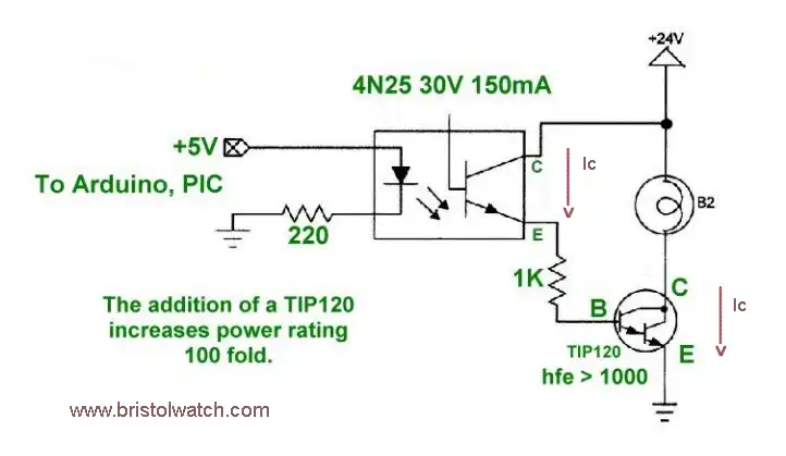
Here we drive a NPN Darlington power transistor. With a gain of 1000 very little base current is needed to be switched though the 4N25. The TIP120 has a maximum base current (Ib) of 150 mA while the 4N25 has a maximum collector current of 150 mA. R2 can be 5600-10,000 ohms.
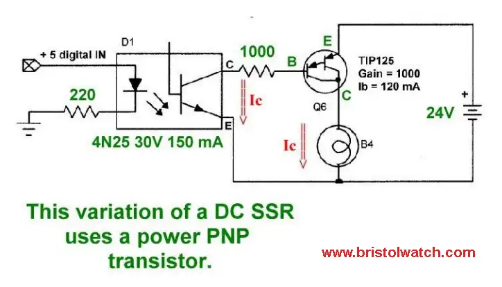
Same as above except we use a PNP Darlington. In this case the base of the TIP125 is switched to ground though a 1000 ohm resistor. Note the 24-volt supply is electrically isolated from the digital circuits.
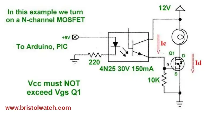
Here we switch a N-channel MOSFET to "sink" the load.
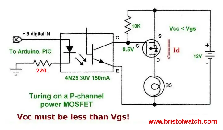
Once again we sever the 12-volt supply totally from the digital circuits. In fact we could have done this with all of the circuits on this page. Here we switch on a P-channel power MOSFET to "source" the load. R6 = 10K and BATT2 is limited to 30 volts because of the 4N25 or the Vgs rating for the MOSFET, which ever is smaller.
![]()
- Quick navigation of this website:
- You Tube Channel
- Basic Electronics Learning and Projects
- Basic Solid State Component Projects
- Arduino Microcontroller Projects
- Raspberry Pi Electronics, Programming
- High Voltage H-Bridge with Photovoltaic Optocouplers
- Optocouplers for TTL-CMOS Logic Level Shifting
- Optical Isolation H-Bridge Motor Controls
YouTube video: Opto-Coupler Theory and Circuits
- ULN2003A Darlington Transistor Array with Circuit Examples
- Tutorial Using TIP120 and TIP125 Power Darlington Transistors
- Driving 2N3055-MJ2955 Power Transistors with Darlington Transistors
- Understanding Bipolar Transistor Switches
- N-Channel Power MOSFET Switching Tutorial
- P-Channel Power MOSFET Switch Tutorial
- H-Bridge Motor Control with Power MOSFETs
- More Power MOSFET H-Bridge Circuit Examples
- Build a High Power Transistor H-Bridge Motor Control
- Added Nov. 16, 2014
- ULN2003A Darlington Transistor Array with Circuit Examples
- Tutorial Using TIP120 and TIP125 Power Darlington Transistors
- Driving 2N3055-MJ2955 Power Transistors
- Understanding Bipolar Transistor Switches
- N-Channel Power MOSFET Switching Tutorial
- P-Channel Power MOSFET Switch Tutorial
- H-Bridge Motor Control with Power MOSFETs
- More Power MOSFET H-Bridge Circuit Examples
- Build a High Power Transistor H-Bridge Motor Control
Web site Copyright Lewis Loflin, All rights reserved.
If using this material on another site, please provide a link back to my site.