Bi-Polar MOSFET Transistor Driver Microcontroller Interfacing
by Lewis Loflin
The output of most digital circuits and micro-processors is only five volts at most a few milli-amps. Most electrical and electronic devices require voltages and currents that will destroy digital circuits, so we must rely on what I'll broadly call driver circuits. Above illustrates a digital output driving a typical low-power light emitting diodes.
On this page we will look at transistor driver circuits using both bipolar transistors and power MOSFETs and will use them as electrical switches. Also note the concept of sink/source as we go along.
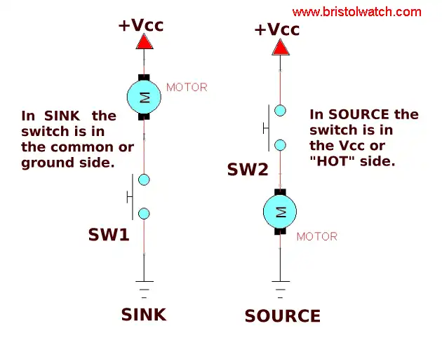
When a "switch" supplies a voltage (on the "hot" side) such as a household light switch, we say the switch "sources" the voltage. If we put the switch on the neutral side of the load, we say we "sink" the voltage. All of the examples below assume a negative shared common.
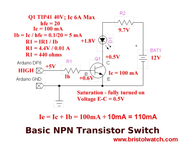
Illustrated above is the most common transistor driver circuit. It consists of a NPN bipolar transistor controlling a high-power light emitting diode connected to a 12-volt battery. We have a negative battery ground tied to digital ground. Note a digital "HIGH" is 5 volts and a digital "LOW" is zero volts.
The "HIGH" is switched to 5 volts inside the micro-controller "chip" while a "LOW" is switched to ground inside the "chip." Another digital state is known as floating that's as the name suggests is attached to nothing.
In this example a digital "HIGH" on the input "sources" a current in the base/emitter of Q1 (limited by R1) which causes a larger current flow in the collector/emitter circuit and through the LED-resistor.
If Q1 has a gain of 50 and the base current through R1 is 5 mA, then the collector current will be 250 mA.
In this case it's only 100 mA limited by the light emitting diode. In many of these transistor circuits R1 ranges from 1000 to 2200 ohms for 5 volts.
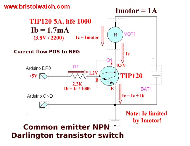
In this example we are using a NPN Darlington transistor. They have very high gain and require little base current. In reality they are two transistors with common collectors and emitter of one tied to the other's base. If each transistor had a gain of 100, then to total gain would be 100 X 100 = 10,000.
Here we would say the transistor "sinks" the current. In the case of using a TIP120 R2 should be 1000-ohms.
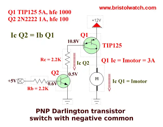
In this example we use a PNP Darlington. (TIP125) When Q2 switches on current flows through Rc switching Q2 on. Here Q2 will "source" the load. In the case of using 12-volts Rc and Rb should be 2200-ohms.
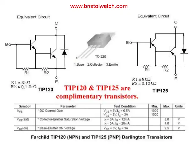
The internal circuits of the above two Darlingtons shows opposite electrical polarities. The diodes are used to protect the transistors from surges created when switching magnetic loads.
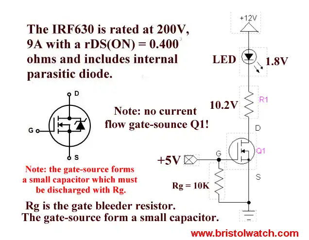
Switching on a MOSFET
Here is the basic driver using a N-channel MOSFET. Unlike bipolar transistors MOSFETs are voltage operated devices, not current operated. An electrical charge (voltage) on the gate (G) relative to the source (S) will switch on the device.
The only purpose of Rg (10K) is to bleed-off any remaining charge on gate terminal to shut the transistor off. In this case we "sink" the load.
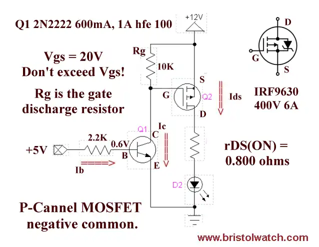
In this example we use a P-channel power MOSFET. The source terminal (S) is connected to the positive of the power supply and while Q1 is off (no 5 volts in) we have 12-volts on the collector (C) of Q1.
When 5 volts is supplied Q1 switches on dropping the collector voltage to zero. Q2 will switch on and "source" the load. Rg should be 10,000 ohms.
In summery we have looked at a number of bipolar transistor and MOSFET driver circuits. They all have a flaw of having to be electrically connected to low voltage digital circuits. With opto-isolators we can sever this connection of the higher-voltage power supplies totally from the low-voltage digital circuits if desired.
In fact we can even change the polarity of the higher voltage supplies without regards to the digital circuit's common negative ground.
See Part 2: Opto-Isolated Transistor Drivers for Micro-Controllers.
![]()
- Quick navigation of this website:
- You Tube Channel
- Basic Electronics Learning and Projects
- Basic Solid State Component Projects
- Arduino Microcontroller Projects
- Raspberry Pi Electronics, Programming
- ULN2003A Darlington Transistor Array with Circuit Examples
- Tutorial Using TIP120 and TIP125 Power Darlington Transistors
- Driving 2N3055-MJ2955 Darlington Transistors
- Understanding Bipolar Transistor Switches
- N-Channel Power MOSFET Switching Tutorial
- P-Channel Power MOSFET Switch Tutorial
- H-Bridge Motor Control with Power MOSFETs
- Arduino Controlled IR2110 Based H-Bridge HV Motor Control
- IGBT Based High Voltage H-Bridge DC Motor Control
- More Power MOSFET H-Bridge Circuit Examples
- Build a High Power Transistor H-Bridge Motor Control
- Related:
- N-Channel Power MOSFET Switching Tutorial
- P-Channel Power MOSFET Switch Tutorial
- Test Power MOSFET Transistors, Observations
- Issues on Connecting MOSFETs in Parallel
- Basic MOSFET Transistor Test Circuits
- High Voltage MOSFET Switching Circuits
- Why Your MOSFET Transistors Get Hot YouTube
- Issues on Connecting MOSFETs in Parallel YouTube
- Simple Circuits for Testing MOSFET Transistors YouTube
- Basic Triacs and SCRs
- Constant Current Circuits with the LM334
- LM334 CCS Circuits with Thermistors, Photocells
- LM317 Constant Current Source Circuits
- TA8050P H-Bridge Motor Control
- All NPN Transistor H-Bridge Motor Control
- Basic Triacs and SCRs
- Comparator Theory Circuits Tutorial
Web site Copyright Lewis Loflin, All rights reserved.
If using this material on another site, please provide a link back to my site.