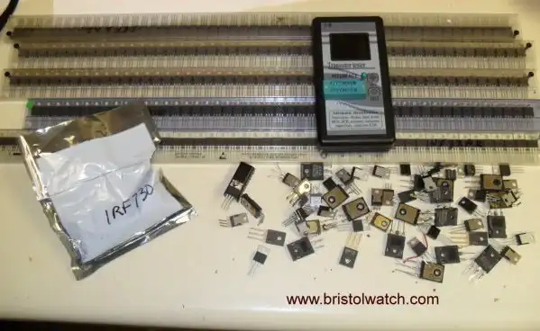
Fig. 1 My MOSFET collection mostly donated by visitor.
Test Power MOSFET Transistors, IGBTs Results, Observations
by Lewis Loflin
I have taken on a number of issues regarding the construction of H-Bridge motor controls and related topics. I designed a simple tri-state CMOS control circuit using two CD4093 ICs.
The idea was not to buy specialized devices. Just use basic transistors, etc.
The output drivers for the motor have been combinations of IGBTs, MOSFETs, and bipolar transistors. The idea was to operate motors at 12-volts, 24-volts, 36-volts, and 48-volts.
The results are as follows:
IGBTs at least those I own shouldn't be used. They have a high voltage drop (Vce ~2V) and are better used for higher voltage switching.
See Insulated Gate Bipolar Transistor IGBT Circuits and H-Bridge schematic with Darlington-IGBT Transistor Outputs.
For motor voltages below 15-volts use a use MOSFETs: IRF4905 for the p-channel and an IRFZ44N for the n-channel.
For voltages above 15-volts use the opto-coupler-Darlington transistor circuit for the p-channel and an IRFZ44N. See Driving Darlington Transistors with Optocouplers
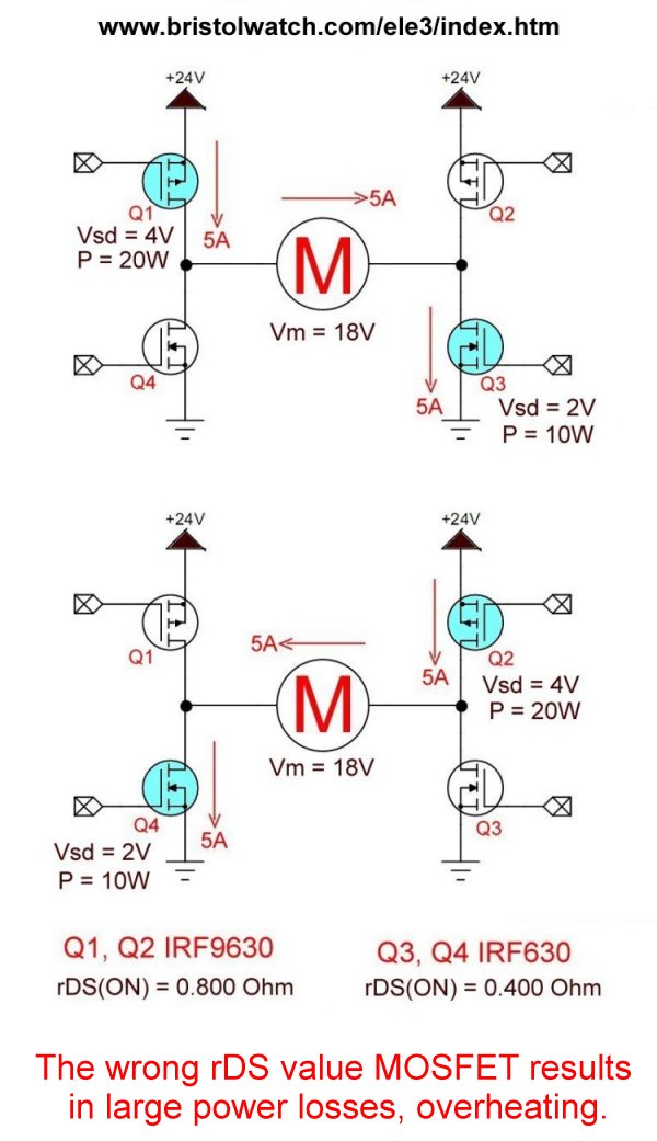
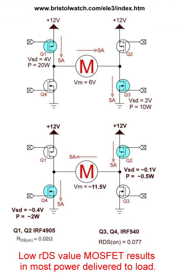
The issue comes down to rDS(on) resistance. Use as low a values as possible. See the following two graphics:
High rDS waste power cause overheating.
Low rDS delivers the most power to the load.
Variable power supply used in test circuits and videos:
LM2575 Simple Switching Voltage Regulators
LM2575 Simple Switching Voltage Regulators YouTube Video
- Related videos and webpages.
- Issues on Connecting MOSFETs in Parallel
- Issues on Connecting MOSFETs in Parallel YouTube Video
- Simple Circuits for Testing MOSFET Transistors YouTube Video
- N-Channel Power MOSFET Switching Tutorial
- P-Channel Power MOSFET Switch Tutorial
See From Basic Digital Circuits to H-Bridge Motor Controls.
Special thanks to Paul for the MOSFETs!
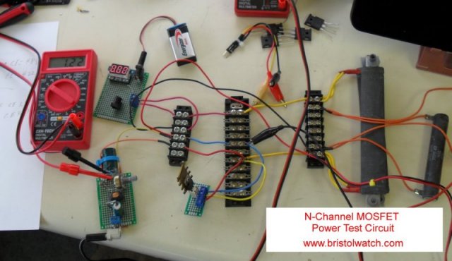
Fig. 2 N-Channel MOSFET test setup on my workbench.
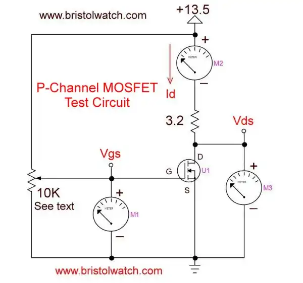
Fig. 3 N-Channel MOSFET test circuit diagram.
In Fig. 3 the LM2575 Simple Switching Voltage Regulator replaced the 10K pot. This must connected to its own separate supply such as a cheap plug in the wall power supply. Observe polarity. Positive to gate negative to ground.
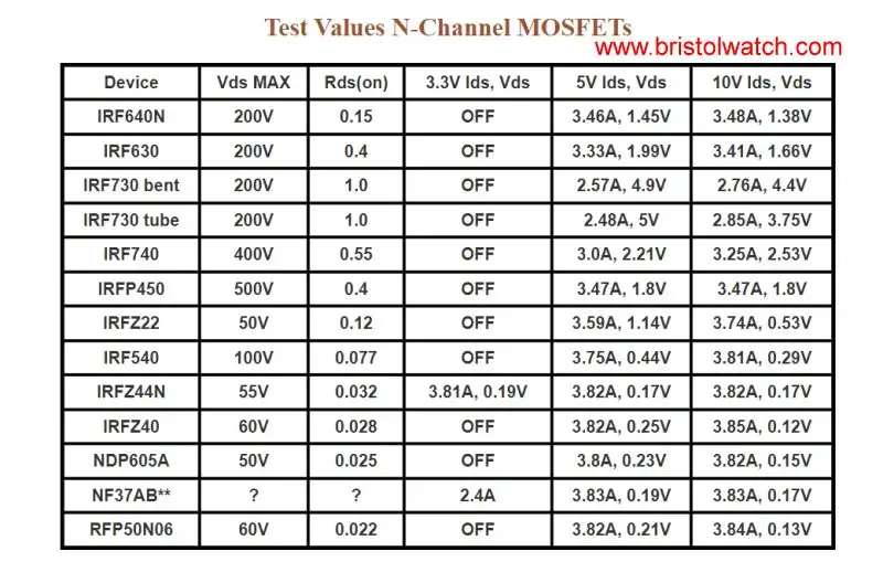
Fig. 3b
Observation: low rDS(on) MOSFETs are low voltage in general 55-60 volts. For higher voltage we often have higher rDS(on).
Many of the devices are easy to parallel but be aware gate-source capacitance, etc. add together.
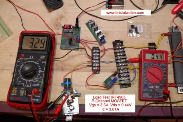
Fig. 4 P-Channel MOSFET test setup on my workbench.
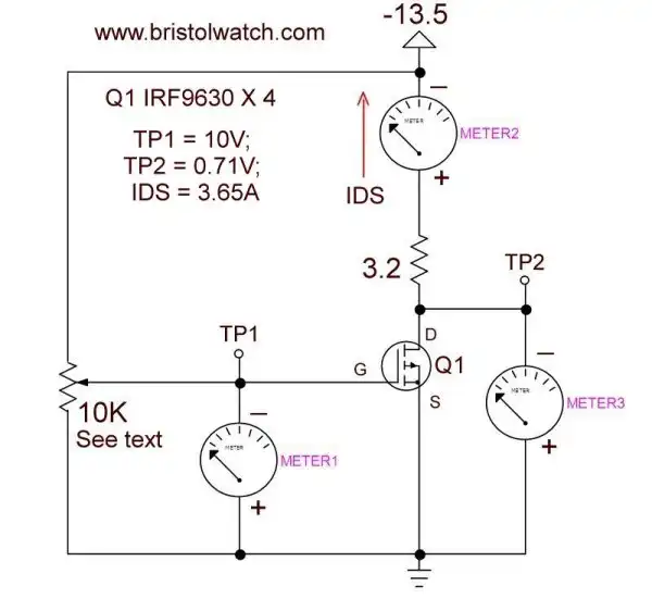
Fig. 5 P-Channel MOSFET test circuit diagram.
In Fig. 5 the LM2575 Simple Switching Voltage Regulator replaced the 10K pot. This must be connected to its own separate supply such as a cheap plug in the wall power supply. Observe polarity. Negative to gate positive to ground.
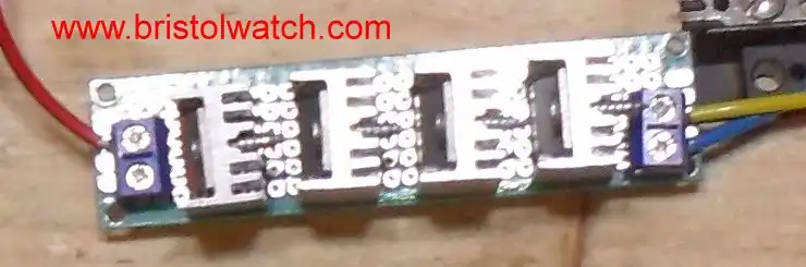
Fig. 6 Four IRF9630 MOSFETs in parallel.
P-channel MOSFETs like n-channel can be paralleled for low rDS(on) as shown above.
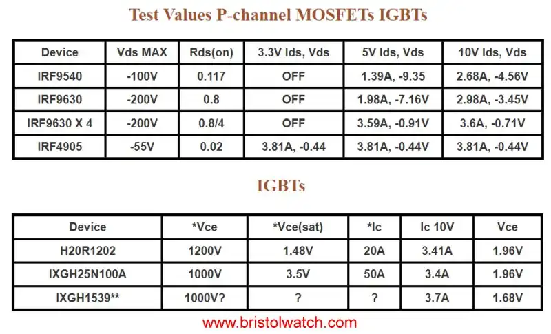
Fig. 6b
Test Values P-channel MOSFETs IGBTs
Because I could use the same test setup for IGBTs as n-channel MOSFETs I tested those I had.
Conclusion: IGBTs don't work directly with 3.3V and 5V micro-controllers such as Arduino. At least 7-volts is required for turn on. The high Vce of 1.5V to 2V can waste power.
IGBTs do differ from MOSFETs with both positive flow and electron flow could deliver more power even at 2V Vce to the load. They are really designed for high-voltage switching.
* from spec sheet.
** no data found.
Also see Insulated Gate Bipolar Transistor IGBT Circuits Tutorial.
Download graphic mosfet_test2.jpg
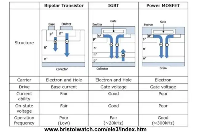
Fig. 7 Comparison IGBT, MOSFET, bipolar transistor current flow.
As shown in Fig. 7 MOSFETs are electron flow only devices only.
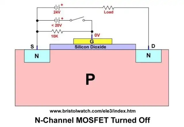
Fig. 8 N-channel MOSFET turned off.
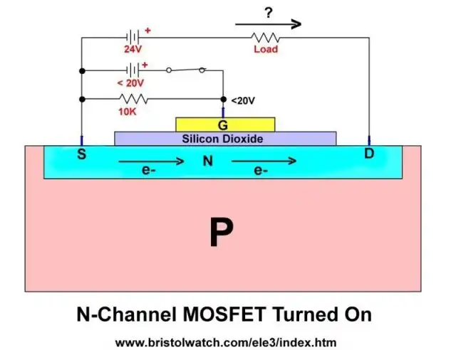
Fig. 9 N-channel MOSFET turned on.
- Youtube videos:
- Driving High-Power Darlington Transistors
- Four MOSFET Tri-State Switch
- Overview Toshiba IGBT Application Notes
- MOSFETs and Electron Flow
- 3.3 Volt Logic Controls H-Bridge TTL Input
- H-Bridge Driving Large Motor
- Simple Digital Interface Circuits
- Optocoupler Interfacing H-Bridge Circuits
- Why Your MOSFET Transistors Get Hot
- Exploring Solid State Relays and Control Circuits
- Comparing Photo Triac, Photo SCR Opto-Couplers
- Light Activated SCR Based Optocouplers Circuit Examples
- Silicon Controlled Rectifier Review and Circuits
- Silicon Controlled Rectifiers Connected as Power Triacs
- Insulated Gate Bipolar Transistor IGBT Circuits
- Current Limiter Circuits for Opto-Coupler LEDs
- VOM1271 Photovoltaic MOSFET Driver Circuits
- Current Limiter Allows Safe Testing of Zener Diodes, LEDs
- 3 Amp LM741 Op-Amp Constant Current Source
- Bidirectional Solid State Relay Circuits
- Simple Solid State Relay for Low Power LED 120V Lamps
- Build High Power MOSFET Directional Switch Relay
- Optical Isolation of H-Bridge Motor Controls
- All NPN Transistor H-Bridge Motor Control
- Basic Transistor Driver Circuits for Micro-Controllers
- ULN2003A Darlington Transistor Array with Circuit Examples
- Tutorial Using TIP120 and TIP125 Power Darlington Transistors
- Driving 2N3055-MJ2955 Power Transistors with Darlington Transistors
- Understanding Bipolar Transistor Switches
- N-Channel Power MOSFET Switching Tutorial
- P-Channel Power MOSFET Switch Tutorial
- Build a Transistor H-Bridge Motor Control
- H-Bridge Motor Control with Power MOSFETS
- More Power MOSFET H-Bridge Circuit Examples
- Build a High Power Transistor H-Bridge Motor Control
- H-Bridge Motor Control with Power MOSFETS Updated
- Opto-Isolated Transistor Drivers for Micro-Controllers
- Comparator Theory Circuits Tutorial
- Constant Current Circuits with the LM334
- LM334 CCS Circuits with Thermistors, Photocells
- LM317 Constant Current Source Circuits
- TA8050P H-Bridge Motor Control
- All NPN Transistor H-Bridge Motor Control
- Basic Triacs and SCRs
- Comparator Hysteresis and Schmitt Triggers
- Comparator Theory Circuits Tutorial
- Photodiode Circuits Operation and Uses
- Optocoupler MOSFET DC Relays Using Photovoltaic drivers
- Connecting Crydom MOSFET Solid State Relays
- Photodiode Op-Amp Circuits Tutorial
- Optocoupler Input Circuits for PLC
- H11L1, 6N137A, FED8183, TLP2662 Digital Output Optocouplers
- Optical Isolation of H-Bridge Motor Controls
- All NPN Transistor H-Bridge Motor Control
© Copyright 2019 Lewis Loflin E-Mail