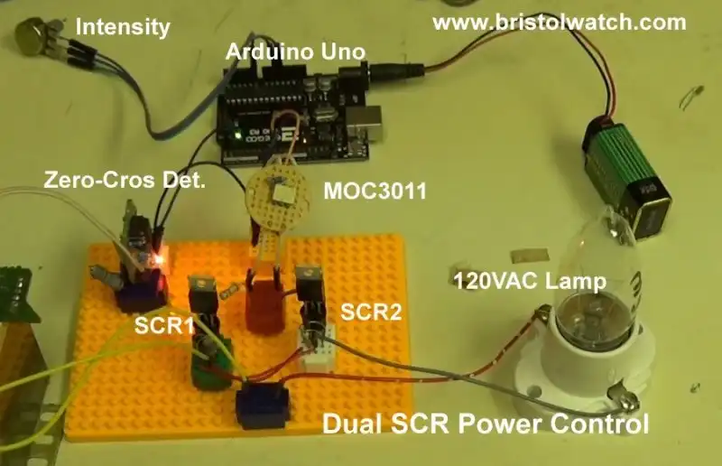
Fig. 1
Silicon Controlled Rectifiers Connected as a Power Triac
by Lewis Loflin
Silicon-controlled rectifier (SCRs) are used for high power AC switching. When used in pairs to simulate their Triac cousins they can switch higher power levels. This is because only one SCR is one at one time thus a lower duty cycle.
Fig. 1 shows the circuit I built and it works. I also found out what doesn't work.
They are also called Thyristors. For more on the properties of SCRs related to these circuits:
- Basic Triacs and SCRs
- Light Activated SCR Based Optocouplers Circuit Examples
- Silicon Controlled Rectifier Review and Circuits
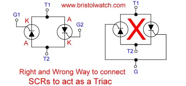
Fig. 2
Fig. 2 illustrates the right and wrong way to connect silicon-controlled rectifiers as Triacs. I built the circuit on the right that is presented across the web. It does not work with both SCRs on all the time.
The better way to view this is the left side where anode is tied to cathode. The two gates must be separate to be properly triggered as individual devices.
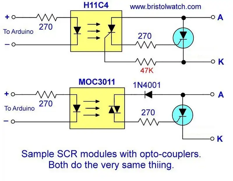
Fig. 3
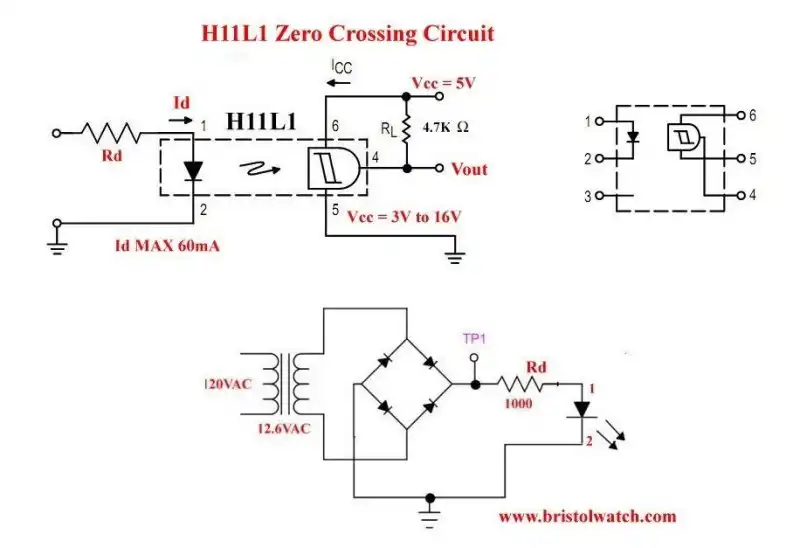
The best option to trigger SCRs or Triacs is with opto-coupler as shown in Fig. 3.
The H11CX photo SCR opto-couplers are designed to the express purpose of triggering SCRs. The problem is many of these parts are hard to find today.
One can use the MOC30XX photo Triac opto-couplers with the addition of a diode in the gate circuit. My test show no practical difference in operation.
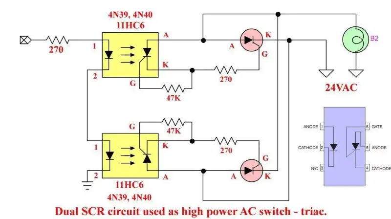
Fig. 4
I also built two separate SCR modules based on Fig. 3 with a single opto-coupler for each SCR. Here I used H11C6 photo SCR opto-couplers with input LEDs connected in series.
These parts are obsolete and I can't find them in 2025. An MOC3010, 11, 12 with a diode can work just as well.

Fig. 5 MOC3010 pin connections and sample circuits.
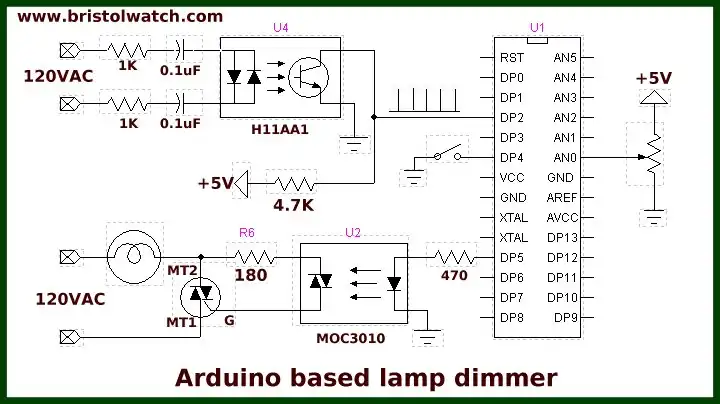
- AC Zero Crossing Detectors for Arduino
- Zero-Crossing Detectors Circuits
- In Depth Look at AC Power Control with Arduino
- Arduino AC Power Control Using Interrupts
- Hardware Interrupts Demo and Tutorial for Arduino
The MOC3010 series optocouplers (including the MOC3011 and MOC3012) comprise a gallium arsenide infrared emitting diode optically coupled to a silicon bilateral switch (Triac).
They are designed for applications requiring isolated triac triggering, low–current isolated AC switching, high electrical isolation (up to 7500 Volts AC peak), high detector standoff voltage, small size, and low cost.
This series includes no zero-crossing circuitry. These are suggested for 115-volt AC (RMS) circuits to include:
• Solenoid/Valve Controls;
• Lamp Ballasts;
• Interfacing Microprocessors to 115 Volt AC Peripherals;
• Motor Controls;
• Static AC Power Switch;
• Solid State Relays;
• Incandescent Lamp Dimmers.
NOTE: This optoisolator should not be used to drive a load directly. It is intended to be a trigger device only.
My Arduino or other microcontroller-based variable AC power control circuits can use these. These circuits should include a separate zero-crossing or phase detector to synchronize with the AC power line.
This is AC phase control, not pulse-width modulation (PWM), used with direct current controls.
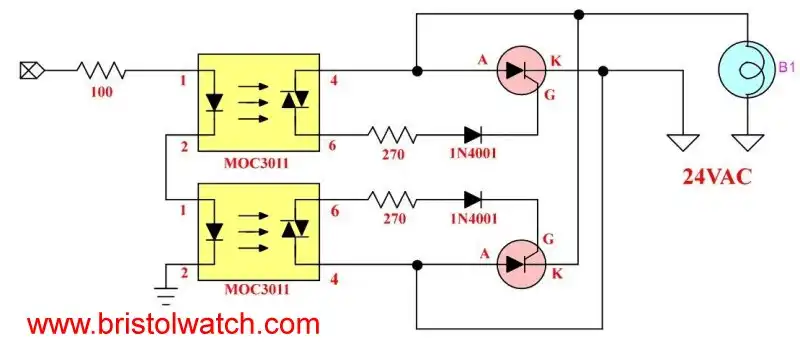
Fig. 6
Fig. 6 does the same thing as Fig. 4 but I use MOC3010 or MOC3011 type Triac opto-couplers with the additional gate diode.
- Exploring Solid State Relays and Control Circuits
- Comparing Photo Triac, Photo SCR Opto-Couplers
- Light Activated SCR Based Optocouplers Circuit Examples
- Silicon Controlled Rectifier Review and Circuits
- Silicon Controlled Rectifiers Connected as Power Triacs
- Insulated Gate Bipolar Transistor IGBT Circuits
- Current Limiter Circuits for Opto-Coupler LEDs
- VOM1271 Photovoltaic MOSFET Driver Circuits
- Current Limiter Allows Safe Testing of Zener Diodes, LEDs
- 3 Amp LM741 Op-Amp Constant Current Source
- Bidirectional Solid State Relay Circuits
- Simple Solid State Relay for Low Power LED 120V Lamps
- Build High Power MOSFET Directional Switch Relay
- Optical Isolation of H-Bridge Motor Controls
- All NPN Transistor H-Bridge Motor Control
- Basic Transistor Driver Circuits for Micro-Controllers
- ULN2003A Darlington Transistor Array with Circuit Examples
- Tutorial Using TIP120 and TIP125 Power Darlington Transistors
- Driving 2N3055-MJ2955 Power Transistors with Darlington Transistors
- Understanding Bipolar Transistor Switches
- N-Channel Power MOSFET Switching Tutorial
- P-Channel Power MOSFET Switch Tutorial
- Build a Transistor H-Bridge Motor Control
- H-Bridge Motor Control with Power MOSFETS
- More Power MOSFET H-Bridge Circuit Examples
- Build a High Power Transistor H-Bridge Motor Control
- H-Bridge Motor Control with Power MOSFETS Updated
- Opto-Isolated Transistor Drivers for Micro-Controllers
- Comparator Theory Circuits Tutorial
- Constant Current Circuits with the LM334
- LM334 CCS Circuits with Thermistors, Photocells
- LM317 Constant Current Source Circuits
- TA8050P H-Bridge Motor Control
- All NPN Transistor H-Bridge Motor Control
- Basic Triacs and SCRs
- Comparator Hysteresis and Schmitt Triggers
- Comparator Theory Circuits Tutorial
- Photodiode Circuits Operation and Uses
- Optocoupler MOSFET DC Relays Using Photovoltaic drivers
- Connecting Crydom MOSFET Solid State Relays
- Photodiode Op-Amp Circuits Tutorial
- Optocoupler Input Circuits for PLC
- H11L1, 6N137A, FED8183, TLP2662 Digital Output Optocouplers
- Optical Isolation of H-Bridge Motor Controls
- All NPN Transistor H-Bridge Motor Control
© Copyright 2019 Lewis Loflin E-Mail