
Fig. 1 Comparator based Schmitt Trigger.
Comparator Hysteresis and Schmitt Triggers
by Lewis Loflin
Hysteresis is defined as:
For slow time changing input signal, an output oscillation can appear while the input signal remains close to the reference voltage. Also low amplitude signal on high impedance can cause oscillations due to noise background.
Such unwelcome behavior can be solved by hysteresis. The principle of hysteresis consists of two different input threshold voltages depending on actual output state.
Here I'll concentrate on examples not followed on my Comparator Circuits Examples Tutorial.
In Fig. 1 we have a comparator based Schmitt trigger which are used to assure clean switching with noisy or erratic signals. When the input voltage on TP2 is less than TP1 the comparator is in the OFF condition. TP3 is pulled up to nearly 12-volts by R4 a 3K resistor.
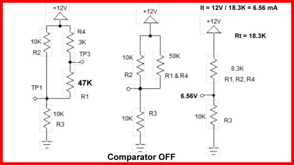
Fig. 2
Fig. 2 illustrates how when the comparator is OFF as R4 and R1 form a series 30K which is in parallel with R2 shifting TP1 (Vref) to 6.56-volts.
Without R1 Vref would be 6-volts.
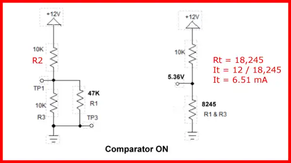
Fig. 3
When the comparator is ON TP3 is switched to ground through the internal open collector transistor where 47K resistor R1 is now in parallel with 10K resistor R3 forming a total resistance of 8245 ohms. This drops Vref on TP1 to 5.36-volts.
It takes 6.56-volts on Vin to turn ON the comparator but the voltage will have to drop to 5.36-volts to turn off. This produces a switching gap or hysteresis value of ~1.2-volts helping to assure stable operation.
A Hall sensor in its most basic form is an analog integrated circuit. It consists of a Hall plate that outputs a "transverse" voltage based on the intensity of a magnetic field - polarity is dependant on magnetic polarity.
It also consists of a high gain differential amplifier because the generated voltage is small. The output voltage is analog usually centered around half the power supply voltage.
The addition of a Schmitt trigger with a properly set hysteresis will create a Hall switch or Hall latch. They often have an open collector output transistor.
The Schmitt triggers used here are based on an analog comparator. These can be built from operational amplifiers (op-amps) like the LM358 or LM741.
Or one can use the LM311 or LM339 quad comparator. The have open collector outputs unlike the LM311/LM741.
Often considered "digital" at this point we have in reality a one-bit analog-to-digital converter.
- Comparator Theory Circuits Tutorial
- Comparator Hysteresis and Schmitt Triggers
- Voltage Comparator Information And Circuits
- Looking at Window Comparator Circuits
![]()
- Quick navigation of this website:
- You Tube Channel
- Basic Electronics Learning and Projects
- Basic Solid State Component Projects
- Arduino Microcontroller Projects
- Raspberry Pi Electronics, Programming
- Connecting Transformers in Series-Parallel
- Build an Adjustable 0-34 volt power supply with the LM317
- AC Power Supply Rectification
- Basic Power Transformers
- Transistor-Zener Diode Regulator Circuits
- Tips for the LM78XX Series Voltage Regulators
- Bi-Polar Power Supplies
- Connecting Series-Parallel Batteries
- Build Autotransformer-Variac AC and DC Power Supply
- Understanding Unijunction Transistors Theory Operation
- Unijunction Transistor SCR Photo Flash Control Circuit
- Basic Triacs and SCRs
- Solid State AC Relays with Triacs
- Light Activated Silicon Controlled Rectifier (LASCR)
- Photo Detector Devices:
- Photodiode Circuits Operation and Uses
- Photodiode Op-Amp Circuits Tutorial
- Photo Voltaic Tutorial MOSFET Output Solid State Relays
- Added Nov. 16, 2014
- ULN2003A Darlington Transistor Array with Circuit Examples
- Tutorial Using TIP120 and TIP125 Power Darlington Transistors
- Driving 2N3055-MJ2955 Power Transistors with Darlington Transistors
- Understanding Bipolar Transistor Switches
- N-Channel Power MOSFET Switching Tutorial
- P-Channel Power MOSFET Switch Tutorial
- More Power MOSFET H-Bridge Circuit Examples
- Build a High Power Transistor H-Bridge Motor Control
Web site Copyright Lewis Loflin, All rights reserved.
If using this material on another site, please provide a link back to my site.