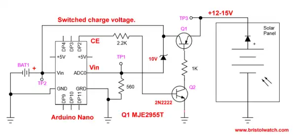
Arduino Solar Battery Charge Controller
Connecting Series-Parallel Batteries Tutorial
by Lewis Loflin
This is an introduction to how to properly connect batteries and cells in series or parallel for greater voltage or current. I'll begin with an explanation of terms, then examples, then experiments. I will only deal here with direct current (DC) devices only. This page has been updated September 2, 2011.
Terms: a cell is an individual electric device. This can be a flashlight cell such as AAA, AA, C, or D cells, or solar cells or even single thermoelectric cell. A battery is a group of two or more cells. They are connected in series positive (+) to negative (-) for greater voltage, or in parallel (+ to + and - to -) for greater current capacity.
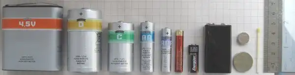
Examples of various cells and batteries.
An everyday examples of a battery is the 9-volt transistor battery, which is six 1.5-volt cells in series. The common automobile battery consists of six 2.1-volt lead-acid cells in series. With a battery of these types that are sealed the failure of a single cell ruins the whole battery.
All batteries consist of individual cells. There are two broad categories of cells:
Primary cells are used once and when discharged are thrown away. Common carbon-zinc and Alkaline are examples of this. There have been attempts to recharge these types of batteries, I wouldn't try this because they could explode or leak.
Secondary cells can be recharged by applying a slightly higher voltage (+ to + and - to - ) to the unit. While a typical auto battery fully charged will read a little over 12.6 volts, the charging system operates at 13-14 volts. Measuring this voltage while the vehicle is idling is a good way to test the charging system.
Examples of these type cells are nickel-cadmium (NiCd), lithium-ion used in many laptop computers, and lead-acid. If these are over charged this can damage the cells and could lead to spewing or explosion. Note that the material in lithium cells is highly reactive to air and water and can cause severe chemical burns.
Never attempt to open a lithium cell and if leaking dispose of quickly. Also not nickel and cadmium are both toxic heavy metals dispose of properly.
Power Considerations
The output voltage of any cell be it chemical, photovoltaic, or thermal is dependant on the materials that make up the cell. So a carbon-zinc cell will produce 1.5 volts regardless of size. It can be a AAA or the size of a tanker truck, it's still 1.5 volts. The size does play into current capacity or the amount of current the cell can deliver.
"The more electrolyte and electrode material there is in the cell the greater the capacity of the cell. Thus, a small cell has less capacity than a larger cell, given the same chemistry (e.g., alkaline cells), though they develop the same open-circuit voltage." (Wiki) This is also known as ampere-hour (Ah) rating.
For example a 6-volt 4.5 Ah battery will produce 4.5-amperes of current for 1 hour or 1 ampere for 4.5 hours. Well, not really. The last few amps often lead to a lower voltage due to increased internal resistance in the cell(s). This is true of either primary or secondary cells. All silicon solar cells produce about .5 volts, but the greater the physical area the greater the current capacity.
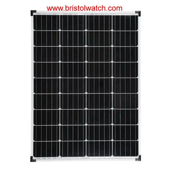
A working Example
Pictured above is a 225 watt solar panel made with 60 solar cells producing 30 volts at 7.5 amps. In this case we wired all 60 cells in series (.5 volts X 60) for a panel to be used with a 24-volt charging system.
We could have wired the same panel for 15-volts for a 12-volt charging system by connecting two groups of 30 cells wired in series, then connecting the two groups in parallel producing 15 amps of current at 15 volts.
Note that these panels are designed to charge lead-acid batteries or an inverter to feed power to the power line. Power is a product of voltage times current, so one solar cell advertised on Ebay is a 3' x 6' poly crystalline solar cell that produces 3.6A or a total of 1.8 watts at .5 volts.
The cells used in the above panel are 6' x 6' and this 30 volt rating is at no load. Batteries be they solar or chemical always have higher open-circuit voltages than they do when being used. When testing any battery do it under load or with a voltmeter set for checking batteries. (It places a load on the battery internally.)
We must consider current in regards to what size wire we want to use. Higher current require a larger gauge conductor or wire thus more expensive wire. In general we want to limit the length of the wire in very heavy current applications. To produce say 1000 watts from a DC-AC inverter (12VDC to 120VAC) makes more sense to use a 24-volt or 48-volt system to cut down on the wire gauge.
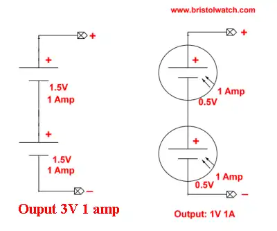
Pictured above are cells in series. They are connected positive to negative and the voltages add while the current or Ampere-hour ratings stay the same. A battery can have any number of cells in series.
Cells in series must be the same type and rating. We can connect a lower capacity cell into the string and get the voltages to add, but lower capacity will quickly discharge that cell acting as a high resistance to the other cells dropping the output voltage.
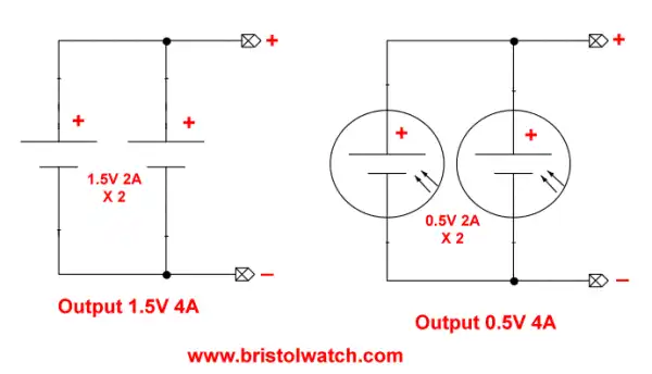
Pictured above are the same cells in parallel. The output voltages stay the same, but the current capacity adds. One can have any number of cells in parallel, but be sure they are the same chemical type and voltage.
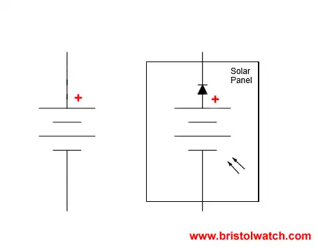
Pictured above are the symbols for batteries. The one on the right is my symbol for a solar battery or solar panel which includes internal blocking diode, which often isn't shown. For the following illustrations I will show the various ways to connect both solar and lead acid cells together. I'll assume the solar cells connected with thirty each in series in two separate panels producing 15 volts at 7.5 amps. I'll also assume four 6-volt lead acid batteries with a current rating of 40 Ah.
Note these need to be deep-cycle or marine batteries, not everyday car batteries.
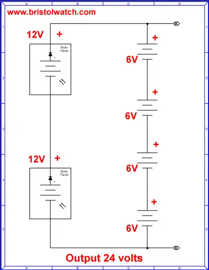
Pictured above is a 24-volt solar charging system. I've wired my two 12-volt solar panels in series and the four 6 volt (actually 6.3) volt 40 Ah batteries in series, connected in parallel with the solar panels.
This will produce about 24 volts at 40 amps for a total power of 960 watts for 1 hour from the four batteries. Or one can have 96 watts for 10 hours, etc.
We would use this to power a 24-volt inverter that converts DC to 120 volts AC for powering AC devices. One model rated at 400 watts is designed for powering solid state items such as computers, radios, etc.
A compact fluorescent light rated at 20 watts would operate for over 48 hours even if no power was being delivered from the solar panels. In daylight power would come from both the batteries and panels.
At the full 400 watts in this example the current would be 16.67 amps to the inverter from the battery bank.
![]()
Diode D1 acts as an electrical "check valve" allowing current to flow in only one direction. This keeps the batteries from discharging through the solar cells when the output voltage drops below the batteries at night.
The arrow points to the N-type semiconductor material in the diode and is not the direction for current flow which is from negative to positive. Most websites on solar have this backwards.
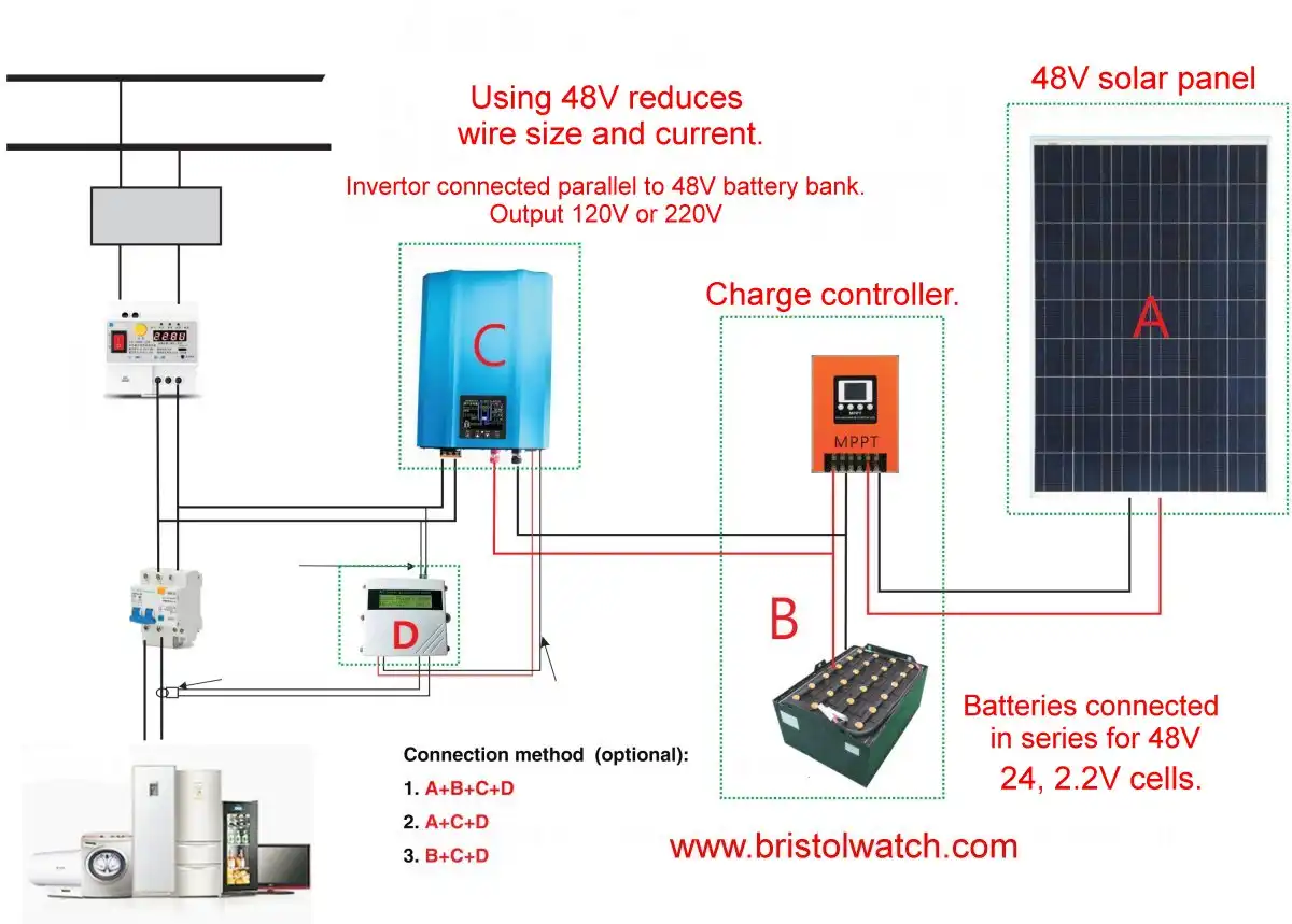
48V inverter battery connections.
Click for larger image.
In fact this entire arrangement be copied then wired in parallel with each other. So four of these wired in parallel can deliver 160 amps at 24-volts or 3840 watts for one hour.
To me this would be a better arrangement because we would use smaller gauge wire to the batteries and smaller blocking diodes saving money. This would also make each individual section more repairable without taking the whole system down.
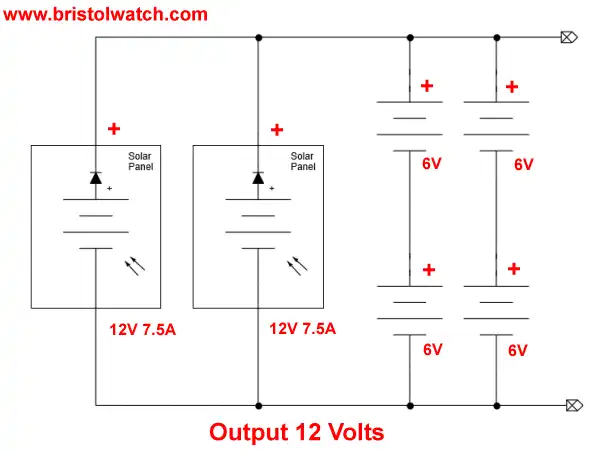
Pictured above is one method to connect our four 6-volt 40 Ah batteries to two solar panels connected in parallel. The two panels can deliver a peak current of 15 amps.
The capacity of the battery bank is now 12-volts at 80 amps. BAT1 and BAT2 are connected in parallel to each other as are BAT3 and BAT4 increasing the current rating to 80 Ah. The two pairs are then connected in series to produce 12 volts at 80 Ah for a total wattage of 960 watts.
Series batteries
PARTS AND MATERIALS
- Two 6-volt batteries
- One 9-volt battery
Actually, any size batteries will suffice for this experiment, but it is recommended to have at least two different voltages available to make it more interesting.
LEARNING OBJECTIVES
- How to connect batteries to obtain different voltage levels
SCHEMATIC DIAGRAM
ILLUSTRATION
INSTRUCTIONS
Connecting components in series means to connect them
in-line with each other, so that there is but a single path for
electrons to flow through them all.
If you connect batteries so that
the positive of one connects to the negative of the other, you will
find that their respective voltages add.
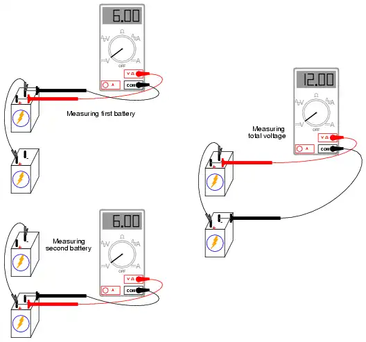
Measure the voltage across
each battery individually as they are connected, then measure the total
voltage across them both, like this:
Try connecting batteries of different sizes in series with each
other, for instance a 6-volt battery with a 9-volt battery. What is the
total voltage in this case?
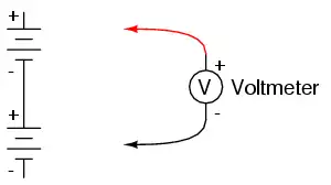
Try reversing the terminal connections of
just one of these batteries, so that they are opposing each other like
this:
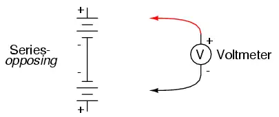
How does the total voltage compare in this situation to the previous
one with both batteries "aiding?" Note the polarity of the total
voltage as indicated by the voltmeter indication and test probe
orientation.
Remember, if the meter's digital indication is a positive
number, the red probe is positive (+) and the black probe negative (-);
if the indication is a negative number, the polarity is "backward"
(red=negative, black=positive).
Analog meters simply will not read
properly if reverse-connected, because the needle tries to move the
wrong direction (left instead of right). Can you predict what the
overall voltage polarity will be, knowing the polarities of the
individual batteries and their respective strengths?
Parallel batteries
PARTS AND MATERIALS
- Four 6-volt batteries
- 12-volt light bulb, 25 or 50 watt
- Lamp socket
High-wattage 12-volt lamps may be purchased from recreational vehicle (RV) and boating supply stores. Common sizes are 25 watt and 50 watt. This lamp will be used as a "heavy" load for your batteries (heavy load = one that draws substantial current).
A regular household (120 volt) lamp socket will work just fine for these low-voltage "RV" lamps.
LEARNING OBJECTIVES
- Voltage source regulation
- Boosting current capacity through parallel connections
ILLUSTRATION
INSTRUCTIONS
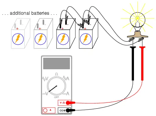
Begin this experiment by connecting one 6-volt battery to the lamp. The lamp, designed to operate on 12 volts, should glow dimly when powered by the 6-volt battery. Use your voltmeter to read voltage across the lamp like this:
The voltmeter should register a voltage lower than the usual voltage
of the battery. If you use your voltmeter to read the voltage directly
at the battery terminals, you will measure a low voltage there as well.
Why is this? The large current drawn by the high-power lamp causes the
voltage at the battery terminals to "sag" or "droop," due to voltage
dropped across resistance internal to the battery.
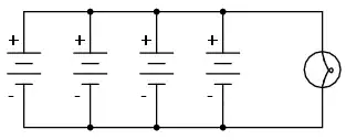
We may overcome this problem by connecting batteries in parallel
with each other, so that each battery only has to supply a fraction of
the total current demanded by the lamp.
Parallel connections involve
making all the positive (+) battery terminals electrically common to
each other by connection through jumper wires, and all negative (-)
terminals common to each other as well.
Add one battery at a time in
parallel, noting the lamp voltage with the addition of each new,
parallel-connected battery:
There should also be a noticeable difference in light intensity as the voltage "sag" is improved.
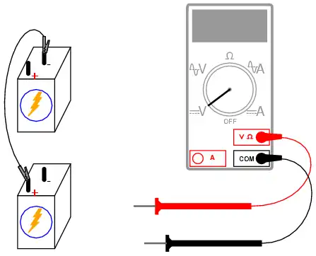
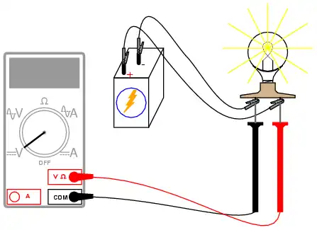
Try measuring the current of one battery and comparing it to the total current (light bulb current). Shown here is the easiest way to measure single-battery current:
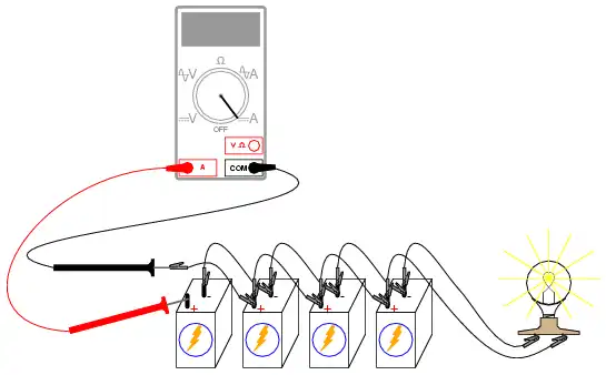
By breaking the circuit for just one battery, and inserting our
ammeter within that break, we intercept the current of that one battery
and are therefore able to measure it.
Measuring total current involves
a similar procedure: make a break somewhere in the path that total
current must take, then insert the ammeter within than break:
Note the difference in current between the single-battery and total measurements.
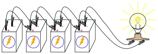
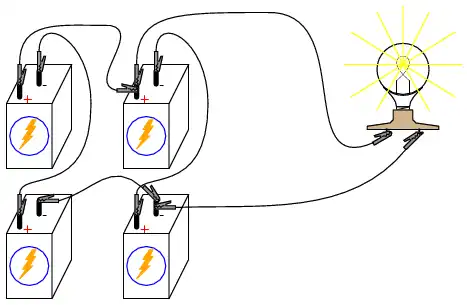
To obtain maximum brightness from the light bulb, a series-parallel
connection is required. Two 6-volt batteries connected series-aiding
will provide 12 volts.
Connecting two of these series-connected battery
pairs in parallel improves their current-sourcing ability for minimum
voltage sag:
Ref. www.allaboutcircuits.com
![]()
- Quick navigation of this website:
- You Tube Channel
- Basic Electronics Learning and Projects
- Basic Solid State Component Projects
- Arduino Microcontroller Projects
- Raspberry Pi Electronics, Programming
- Build Autotransformer-Variac AC and DC Power Supply
- Connecting Transformers in Series-Parallel
- Build an Adjustable 0-34 volt power supply with the LM317
- AC Power Supply Rectification
- Basic Power Transformers
- Transistor-Zener Diode Regulator Circuits
- Tips for the LM78XX Series Voltage Regulators
- Bi-Polar Power Supplies
- Connecting Series-Parallel Batteries
- Related YouTube videos.
- Basic Electronic Power Supplies Part 1
- Basic Electronic Power Supplies Part 2
- Build a low voltage DC power supply Part 3
- AC Power Lab on Series Circuits Part 1
- AC Power Lab on Series Circuits Part 2
- Photo Detector Devices:
- Photodiode Circuits Operation and Uses
- Photodiode Op-Amp Circuits Tutorial
- Photo Voltaic Tutorial MOSFET Output Solid State Relays
- Transistor Driver Circuits
- Opto-Isolated Transistor Drivers for Micro-Controllers
- MOSFET Transistors, IGBTs Observations
- Power transistor tutorials.
- ULN2003A Darlington Transistor Array with Circuit Examples
- Tutorial Using TIP120 and TIP125 Power Darlington Transistors
- Driving 2N3055-MJ2955 Power Transistors with Darlington Transistors
- Understanding Bipolar Transistor Switches
- N-Channel Power MOSFET Switching Tutorial
- P-Channel Power MOSFET Switch Tutorial
- More Power MOSFET H-Bridge Circuit Examples
- Build a High Power Transistor H-Bridge Motor Control
Web site Copyright Lewis Loflin, All rights reserved.
If using this material on another site, please provide a link back to my site.