Fig. 1
Autotransformer-Variac AC-DC Power Supply
by Lewis Loflin
Known as an autotransformer or variac this is a single winding transformer. It can be step-up or step-down. A variac can have taps or a slider. In the past these were also referred to as rheostats. Variac is a trademark of General Radio from the 1930s.
Here I am interested only in a single phase slider type variac. (Fig. 4 below.) It is useful for producing a variable AC voltage that can be rectified-filtered for a variable direct current output.
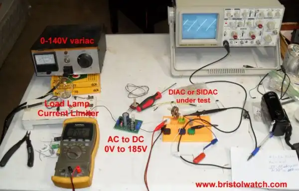
Fig. 1 upper left corner illustrates a B&K Model 1653 power supply. It incorporates a variac and an isolation transformer.
That eliminates the greatest problem with an autotransformer - lack of electrical isolation from the "hot" side of the AC line.
This not only creates a shock hazard but could damage my oscilloscope or other power line connected test equipment.
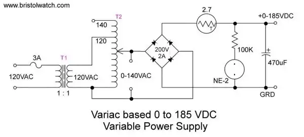
Fig. 2
I'm doing a number of higher voltage test circuits and need higher variable DC voltage up to 180-volts DC.
Fig. 2 is a schematic for building your own isolated variable AC-DC power supply.
T2 and T1 exist within the B&K Model 1653 while the other parts are on the small green circuit board in the center of Fig. 1.
The B&K Model 1653 was sold in the early 1980s and similar boxes today are expensive, may not have an actual autotransformer.
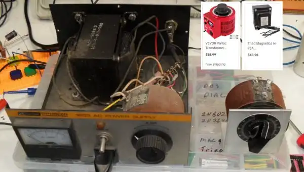
Fig. 3
One can buy separate parts as shown in Fig. 3 upper right corner.
Any bridge rectifier of sufficient current and voltage will work and the capacitor rating must be at least 200-volts.
If one buys the unit with no case ($30-$50+ lower right corner) and the separate isolation transformer all can be installed in a single metal case.
For more technical information I quote,
An autotransformer is an electrical transformer with only one winding. The "auto" (Greek for "self") prefix refers to the single coil acting alone, not to any kind of automatic mechanism. In an autotransformer, portions of the same winding act as both the primary winding and secondary winding sides of the transformer. In contrast, an ordinary transformer has separate primary and secondary windings which have no metallic conducting path between them.
The autotransformer winding has at least three taps where electrical connections are made. Since part of the winding does "double duty", autotransformers have the advantages of often being smaller, lighter, and cheaper than typical dual-winding transformers, but the disadvantage of not providing electrical isolation between primary and secondary circuits. Other advantages of autotransformers include lower leakage reactance, lower losses, lower excitation current, and increased VA rating for a given size and mass.
Ref. Wiki.
- Load Lamp Safely Allows Safer Electronic Testing
- Warning About Electrical Shock and How to Prevent It
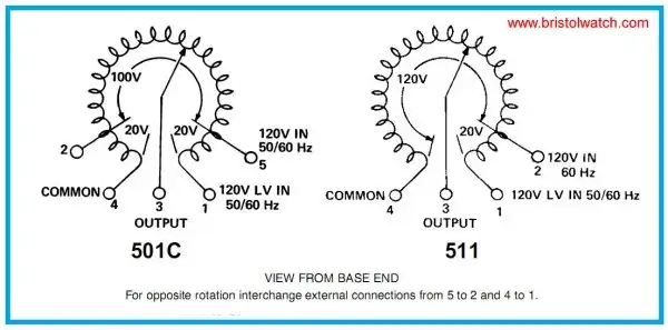
Fig. 4
The remaining images are self-explanatory. They relate to my YouTube Video.
See Build Autotransformer-Variac AC and DC Power Supply
![]()
- Quick navigation of this website:
- You Tube Channel
- Basic Electronics Learning and Projects
- Homepage Lewis Loflin
- Follow on X
- Skeptic Site
- Religion 1
- Religion 2
- Coils for Highly Selective Crystal Radio
- Neon (NE-2) Circuits You Can Build
- Understanding Xenon Flashtubes and Circuits
- Hall Effect Magnetic Switches and Sensors
- Transistor-Zener Diode Regulator Circuits
- Build an Adjustable 0-34 volt power supply with the LM317
- Simple 2 Transistor LED Flasher Circuit
- LM2575 Simple Switching Voltage Regulators
- LM317 Constant Current Source for Lighting LEDs
- IGBT Based High Voltage H-Bridge DC Motor Control
- Arduino Controlled IR2110 Based H-Bridge HV Motor Control
- Understanding Unijunction Transistors Theory Operation
- Arduino Measures Current from Constant Current Source
- Constant Current Source Theory Testing
- Review Ohm's Law for Trouble-Shooting CCS Circuits
- Arduino Power Magnetic Driver Board for Stepper Motors
- Arduino Controlled Power Constant Current Source
- Theory and Operation of Capacitors
Related video to above:
- Measure Current from Constant Current Source with Arduino
- Constant Current Source Multimeter Trouble Shooting
- Ohm's Law Review for Constant Current Source
- Arduino Unipolar Stepper Motor Driver Board with Arduino Code
- Arduino Controlled Constant Current Source
- LM317 Adjustable Current Boost Power Supply
- Constant Current Circuits LM334, LM317
- Build LM317 0-34 Volt Power Supply
- LM334 Constant Current Source with Resistive Sensors
- LM317 High Power Constant Current Source Circuit
- LM317 Constant Current Source Circuits
- Test SCRs and Triacs
- Basic MOSFET Transistor Test Circuits
- High Voltage MOSFET Switching Circuits
- 3 Amp LM741 Op-Amp Constant Current Source
- Current Limiter Testing of Zener Diodes
- Current Limiter for Opto-Coupler Inputs
- LM317 CCS for Light Emitting Diodes
Web site Copyright Lewis Loflin, All rights reserved.
If using this material on another site, please provide a link back to my site.