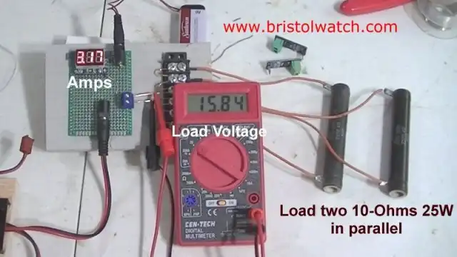
Fig. 1 Test setup for constant current source.
Click for a larger image.
Constant Current Source Theory Testing
by Lewis Loflin
Note: click on any image for larger view.
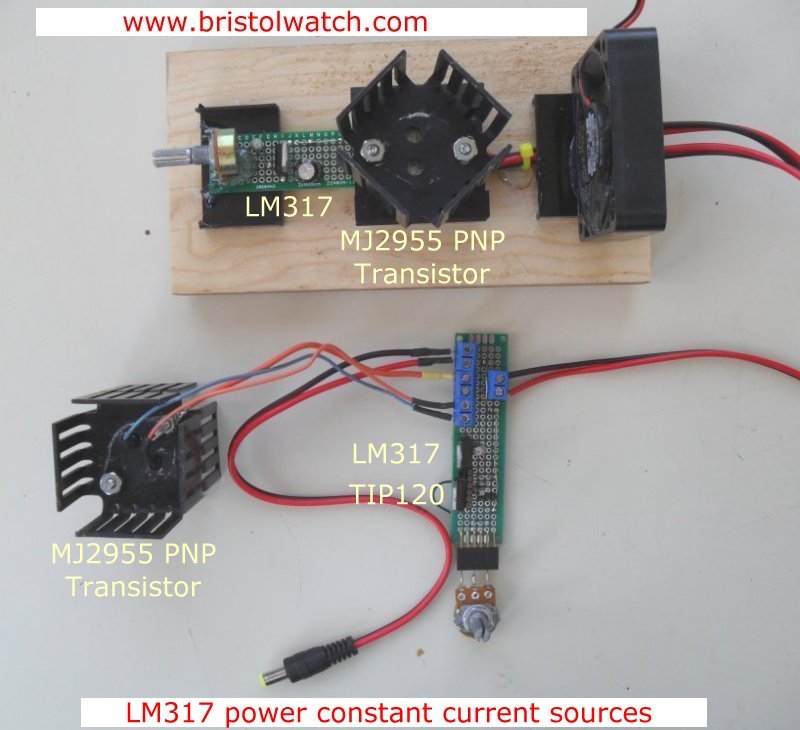
I have two constant current source assemblies. One is for use with a microcontroller, the other simply manual adjustment.
See the following photo for the two: Constant Current Sources I built. The one on the wooden board is the one used here.
The smaller PC board assembly is for my webpage Arduino Controlled Power Constant Current Source.
If one is new to electronics or need a short review of current and voltage is series parallel circuits see my webpage Review Ohm's Law for Trouble-Shooting CCS Circuits.
This is based on my earlier work with this device and the link to that page and a YouTube video:
Here I'll update and go beyond the old design and look at uses, limitations, and theory of operation.
Let's define what a constant current source is off the web:
"A constant current source is a power source which provides a constant current to a load, even despite changes and variance in load resistance...A constant current source is, thus, a very valuable component because it can supply steady current even if there are changes in resistance, even a wide variance in the resistance. This comes in use when a circuit needs a steady current supply, without fluctuations."
It goes far beyond that. When developing or trouble shooting a current limiter, and that is what it really is, protects components from damage. In fact I use mine when constructing and programming H-bridge motor control circuits.
In fact I used my older CCS to build the newer version in case of wiring mistakes. In one case I dead shorted the output with no harm to any part.
Fig. 1 is my test setup. There is much more going on than the definition suggests.
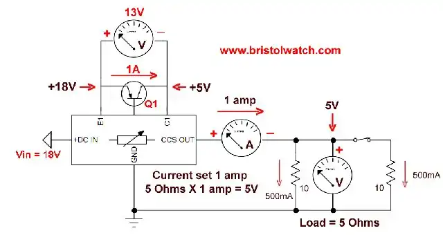
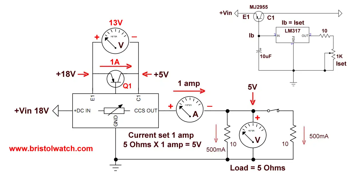
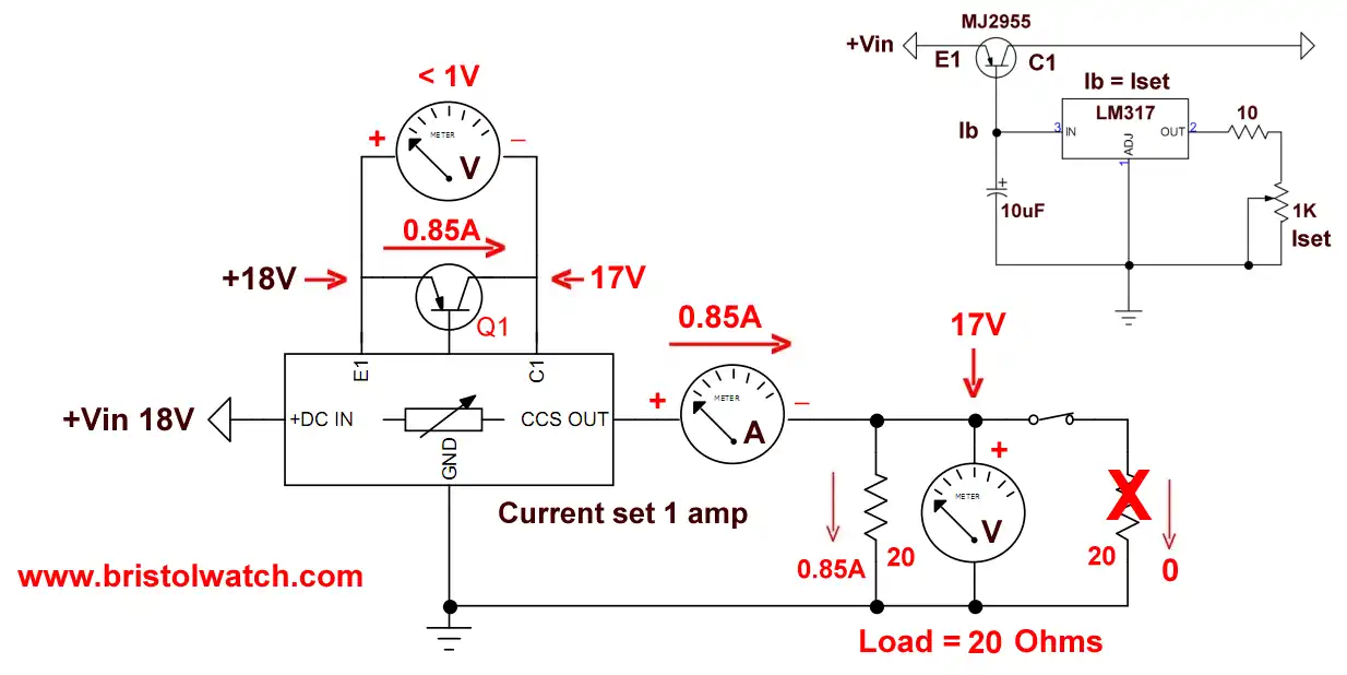
Fig. 2 Schematic to CCS test setup..
Click for a larger image.
Fig. 2 is the schematic to the test setup. Note the upper right corner is the CCS schematic. It consists of a PNP pass transistor and an LM317 used as a variable constant current source.
The LM317 controls the base-emitter current of Q1. That in turn sets the emitter-collector current which is the output current.
The Iset control sets overall output current.
The input voltage is 18-volts. Note the next three images.

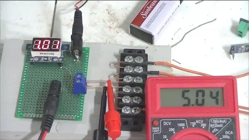
Fig. 3 Adjusted for 1 amp current produces 5-volts with 5-Ohm load..
Click for a larger image.
Fig. 3 illustrates 1 amp through 5-Ohms is 5-volts. The input voltage is 18-volts, so where is my 13-volts?
It is dropped across the pass transistor Q1 where the emitter-collector current is also 1 amp.
The power supply produces a little over 1 amp with the extra for the LM317 circuit.
The load being two, 10-Ohm 25-watt resistors split the 5-watts of power equally. But Q1 drops 13-volts at 1 amp or 13-watts.
Q1's heat sink can get hot and I added a small fan for cooling. Yes there is some drift due to heat with Q1, but is minimal.
The best way to reduce heat generated in Q1 is use a lower input voltage. In the case 8-12-volts is plenty.
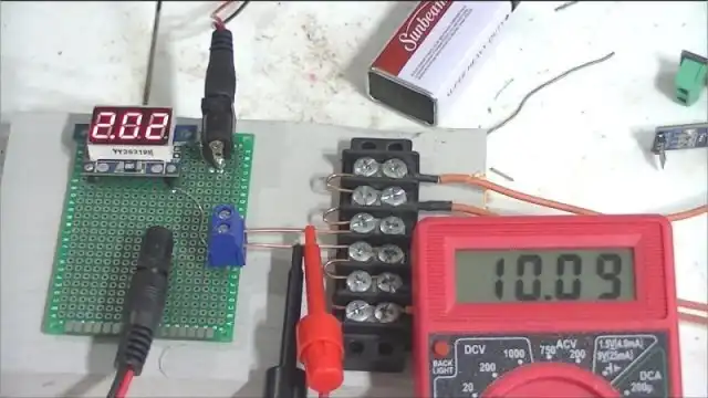
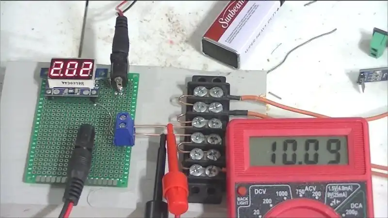
Fig. 4 Adjusted for 2 amps current produces 10-volts with 5-Ohm load.
Click for a larger image.
Fig. 4 we supply 2 amps to the load producing 10-volts. The load receives 20-watts (voltage times current) split between the two parallel 10-ohm resistors.
Q1 drops 8-volts at 2 amps for 16-watts.
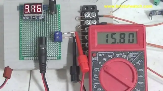
Fig. 5 Adjusted for 3 amps current produces 15-volts with 5-Ohm load..
Click for a larger image.
Here we have 3 amps delivers 15-volts and 45 watts to the load. Q1 pass transistor dissipates 15-watts.
Note the voltage drop across the load is getting close to the input voltage of 18-volts. Above 16-volts the circuit will no longer regulate or limit the current.
As a general rule load voltage times current must never exceed 85% of the input voltage. This can vary in other circuits but is the rule I follow.
The following three examples illustrate the real world. Remember with 18-volts input and a 5-Ohm load we can deliver a little over 3 amps, over 45-watts to the load.
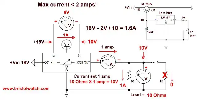
Fig. 6.
Click for a larger image.
Load Resistance versus Input Voltage
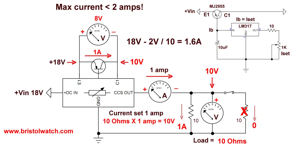
In Fig. 6 I removed one of the 10-Ohm parallel resistors. My load resistance is now 10-Ohms and I adjusted the current for 1 amp. I got 10-volts across the load.
What is my maximum current? Will I get 2 or 3 amps? The answer is no.
Try adjusting for 2 amps the load voltage exceeds the input voltage. The best we can do is 1.6 amps.
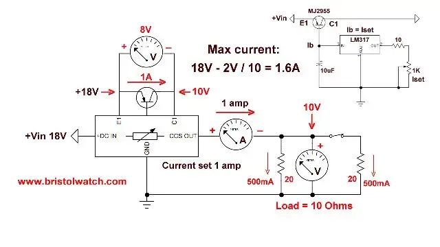
Fig. 7.
Click for a larger image.
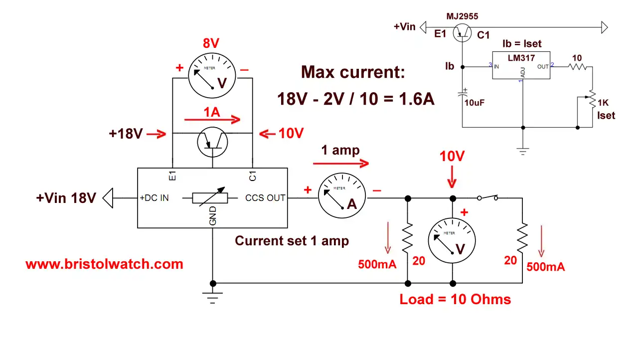
In Fig. 7 two 20-Ohm resistors in parallel produces a 10-Ohm load. Again maximum current is still 1.6 amps.
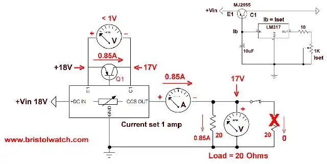
Fig. 8.
Click for a larger image.
In Fig. 8 I removed one 20-Ohm resistor for a load of 20-ohms. My maximum current is ~850mA.
Conclusion
Output voltage from a constant current source is set by the current and load resistance.
Changing load resistance won't change the current, but changes the load voltage. This is limited by the input voltage.
As a rule choose a power supply greater than the needed load voltage. Don't use a 24-volt input to operate a 2-volt load. In my opinion keep the input voltage about 25% above the load voltage if possible.
My test on the circuit also revealed changing the input voltage will change the output voltage. Use a stable input voltage.
A constant current source is NOT a voltage regulator.
![]()
- Quick navigation of this website:
- You Tube Channel
- Basic Electronics Learning and Projects
- Homepage Lewis Loflin
- Follow on X
- Skeptic Site
- Religion 1
- Religion 2
- Coils for Highly Selective Crystal Radio
- Neon (NE-2) Circuits You Can Build
- Understanding Xenon Flashtubes and Circuits
- Hall Effect Magnetic Switches and Sensors
- Transistor-Zener Diode Regulator Circuits
- Build an Adjustable 0-34 volt power supply with the LM317
- Simple 2 Transistor LED Flasher Circuit
- LM2575 Simple Switching Voltage Regulators
- LM317 Constant Current Source for Lighting LEDs
- IGBT Based High Voltage H-Bridge DC Motor Control
- Arduino Controlled IR2110 Based H-Bridge HV Motor Control
- Understanding Unijunction Transistors Theory Operation
- Arduino Measures Current from Constant Current Source
- Constant Current Source Theory Testing
- Review Ohm's Law for Trouble-Shooting CCS Circuits
- Arduino Power Magnetic Driver Board for Stepper Motors
- Arduino Controlled Power Constant Current Source
- Theory and Operation of Capacitors
Related video to above:
- Measure Current from Constant Current Source with Arduino
- Constant Current Source Multimeter Trouble Shooting
- Ohm's Law Review for Constant Current Source
- Arduino Unipolar Stepper Motor Driver Board with Arduino Code
- Arduino Controlled Constant Current Source
- LM317 Adjustable Current Boost Power Supply
- Constant Current Circuits LM334, LM317
- Build LM317 0-34 Volt Power Supply
- LM334 Constant Current Source with Resistive Sensors
- LM317 High Power Constant Current Source Circuit
- LM317 Constant Current Source Circuits
- Test SCRs and Triacs
- Basic MOSFET Transistor Test Circuits
- High Voltage MOSFET Switching Circuits
- 3 Amp LM741 Op-Amp Constant Current Source
- Current Limiter Testing of Zener Diodes
- Current Limiter for Opto-Coupler Inputs
- LM317 CCS for Light Emitting Diodes
Web site Copyright Lewis Loflin, All rights reserved.
If using this material on another site, please provide a link back to my site.