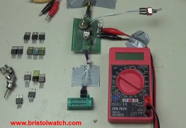
Fig. 1 My SCR-Triac test setup.
How to Test Silicon Controlled Rectifiers, Triacs
by Lewis Loflin
This page is related to three You Tube Videos on simple test circuits for SCRs-Thyristors and Triacs. Most of the explanations are in the videos listed below.
The first part of a three-part lab concerned testing SCRs and Triacs.
A problem came up when my Kuman and MK-168 semiconductor checkers would not test most SCRs, unless they had very sensitive gates, and no triacs at all. At least those I had shown to the right in Fig. 1.
The test assembly used a ZIF socket connected to the home built proto-board in the upper center of Fig. 1. A 25.2 volt A.C. transformer is outside the photo.
A 24-volt lamp is used as a load and measurements are made with a Cen-Tech DVM. A white socket in the center of the board allows one to plug in a TO-220 style SCR or Triac or an external adaptor cable with alligator clips for oddball parts that won't fit it or the ZIF socket.
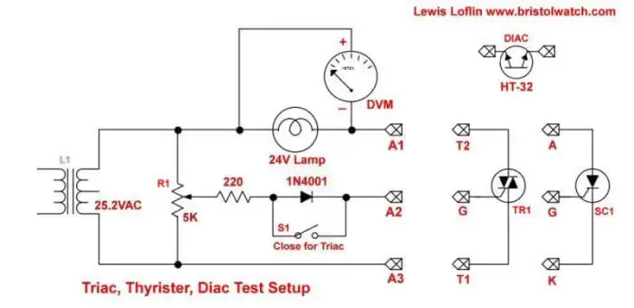
Fig. 2
Fig. 2 is the electrical schematic for the test board. Power is supplied by the transformer and gate current for either device is controlled by R1 a 5K potentiometer. A diode is used for SCR tests and is jumpered for Triac tests.
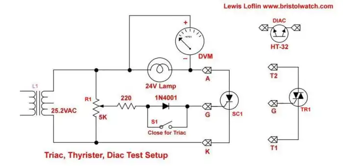
Fig. 3
Testing SCRs
Fig 3 illustrates the connection for testing SCRs S1 is open. When the SCR is fully turned on with R1 is acts as a half-wave rectifier and the DVM will read ~12.4VDC based on the 28VAC from my particular power transformer.
Notice that the gate turn voltage varies from one SCR to the next. Two were very sensitive while some required much greater turn on current for full output voltage to the DVM.
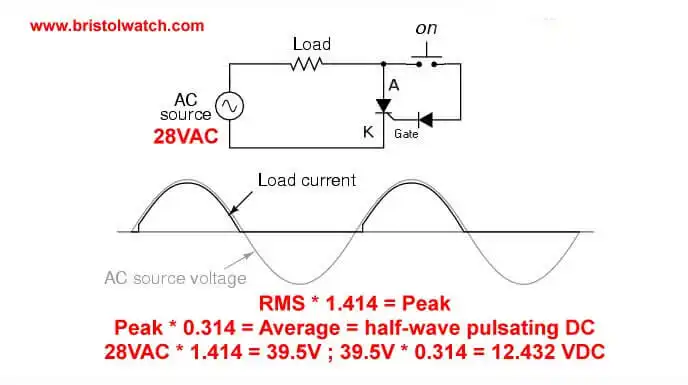
Fig. 4
Fig 4 illustrates an SCR being used as a half-wave rectifier with voltage calculations.
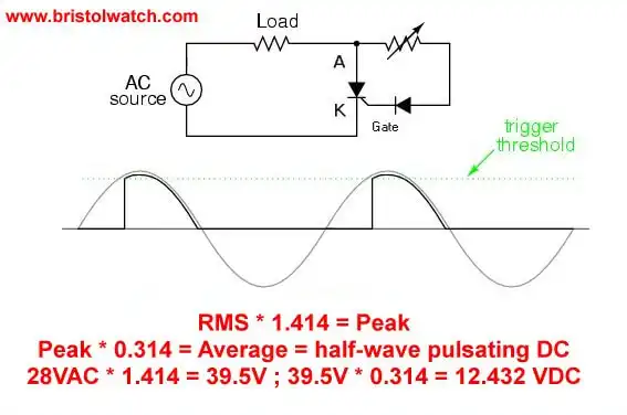
Fig. 5
Fig 5 uses a potentiometer to vary the trigger point on the half-wave. The formula in the slide only works if the SCR is fully on.
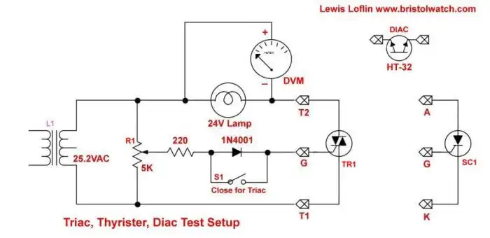
Fig. 6
Fig. 6 illustrates a Triac connected to the test setup. When the Triac is fully turned on by R1 the DVM reads 0 volts DC and when on the AC setting reads 27VAC. (One volt is across the test Triac.)
Be sure S1 is closed!
As the attached video noted when R1 was turned up one side of the Triac switched on and the device acted like an SCR producing a DC voltage. As I continued to adjust R1 the other side also turned on. The lamp became bright, no DC voltage just AC across the lamp.
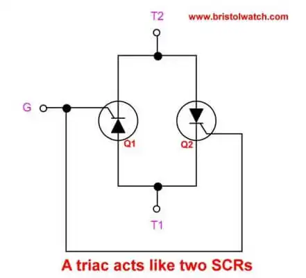
Fig. 7
The answer to the problem is Fig. 7. A Triac acts like two back-to-back SCRs with the gates connected in common. Each "SCR" has a different cut on voltage which is why one turned on and acted like an SCR until the 2nd SCR turned on.
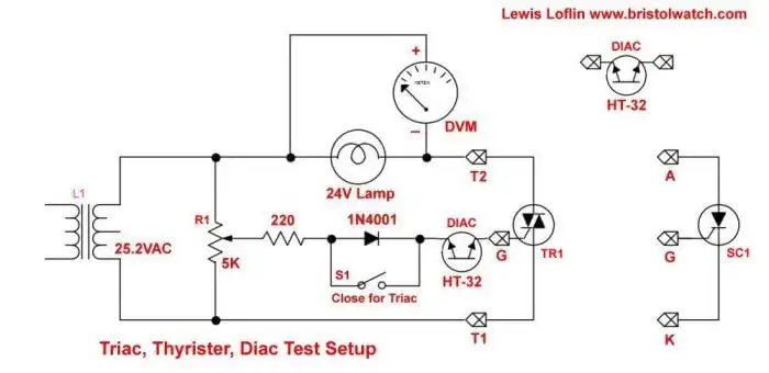
Fig. 8
Fig. 8 our solution to the tun on problem. Let's argue (Fig. 7) Q1 turns on at 22 volts and Q2 at 28 volts. The diac that was inserted into the gate circuit fires at about 30 volts dumping sufficient current into both sides at once.
That switched on Q1 and Q2 together regardless of differing gate turn on voltages.
- Basic Triacs and SCRs
- Solid State AC Relays with Triacs
- Light Activated Silicon Controlled Rectifier (LASCR)
- Light Activated SCR Based Optocouplers Circuit Examples
- Comparing Photo Triac, Photo SCR Opto-Couplers
- Silicon Controlled Rectifier Review and Circuits
- Silicon Controlled Rectifiers Connected as Power Triacs
- You Tube Videos
- How to Check SCRs and Triacs - Simple Circuit Part 1
- Testing SCRs Simple Circuit Part 2
- Testing Triacs Simple Circuit Part 3
- LM317 Adjustable Voltage, Current Boost Power Supply
- Constant Current Circuits LM334, LM317
- Build LM317 0-34 Volt Power Supply
- LM334 Constant Current Source with Resistive Sensors
- LM317 High Power Constant Current Source Circuit
- LM317 Constant Current Source Circuits
- Test SCRs and Triacs
- Basic MOSFET Transistor Test Circuits
- High Voltage MOSFET Switching Circuits
- 3 Amp LM741 Op-Amp Constant Current Source
- Current Limiter Testing of Zener Diodes
- Current Limiter for Opto-Coupler Inputs
- LM317 CCS for Light Emitting Diodes
- Experiments with TL431 Shunt Regulator
- TL431A Precision Current Regulator Circuits
- TL431A Based Current Limiter Constant Current Source Circuits
- TL431A Shunt Regulator Circuits
- Using TL431A Li-Ion Battery Charger Tutorials
- TL431A Lithium-Ion Cell Charging Circuits
- Charging Multi-Cell Lithium-Ion Battery Packs
- TL431 Over-Voltage, Under-Voltage Detector Circuits
- TL431A Constant Current Source Working Circuits Demo
Related YouTube video TL431A Lithium-Ion Cell Charging Circuits
Related YouTube video TL431 Battery Charger Circuit Calculations Revised
Related YouTube video TL431 10-Volt Charger Short Version
Related YouTube video Charging, Charge-Balancing 18V Li-Ion Battery with TL431
Related YouTube video 18.5V Li-Ion Battery Charger with TL431 (short)
- Arduino Measures Current from Constant Current Source
- Constant Current Source Theory Testing
- Arduino Controlled Power Constant Current Source
You Tube Videos
- Adjustable LM317 High Power Current Source
- Current Boost LM317 Adj. Power Supply
- LM317 Constant Current Source Circuits
Other Circuits
- Hall Effect Magnetic Switches and Sensors
- Comparator Theory Circuits Tutorial
- ULN2003A Darlington Transistor Array with Circuit Examples
- Transistor-Zener Diode Regulator Circuits
- AC Power Supply Rectification
- Coils for Highly Selective Crystal Radio
- Neon (NE-2) Circuits You Can Build
- Photodiode Circuits Operation and Uses
- Photodiode Op-Amp Circuits Tutorial
Web site Copyright Lewis Loflin, All rights reserved.
If using this material on another site, please provide a link back to my site.