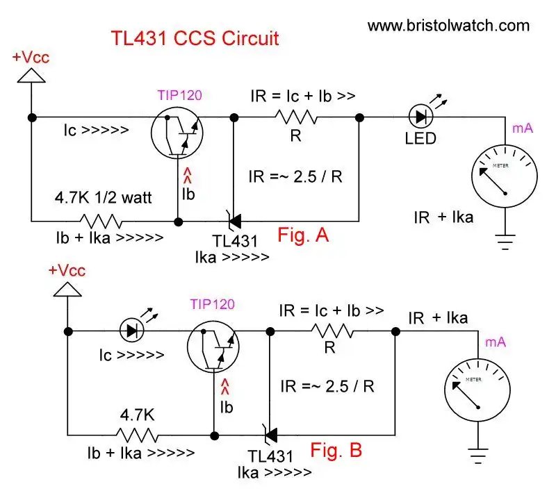
Fig. 1 TL431 current source and current sink schematics.
TL431A Constant Current Source Working Circuits Demo
by Lewis Loflin
For the background on TL431 CCS circuits see TL431A Based Current Limiter Constant Current Source Circuits.
This page concerns the use of the constant current source configuration Fig. 1 A. The NPN transistor used in the specification sheet example, with little useful information, has been replaced by a TIP120 NPN Darlington transistor. This produces better output characteristics than an NPN.
The current formula is 2.5 / R. Figures 2 through 5 below illustrate the test set up and the calculated and measured results for an R value of 15, 47, and 150 Ohms.
The test load is a white power LED that operates at a measured ~2.8V. Notice the smaller value of R the brighter the LED due to higher current. Notice the heat sink on the LED.
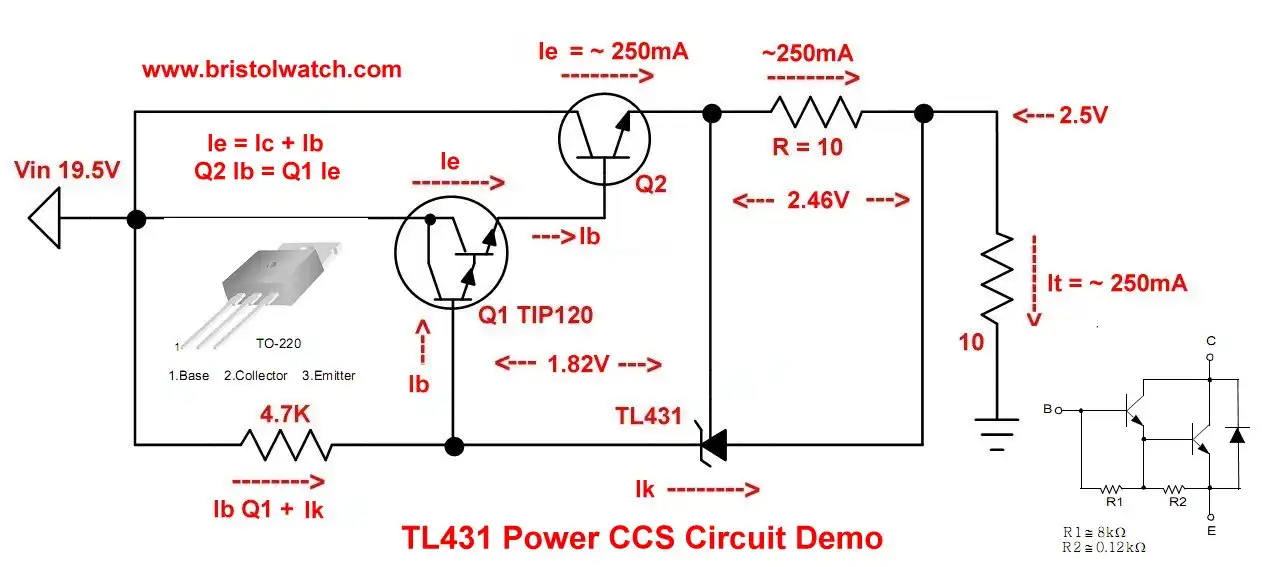
The TL431 cathode and Ref pins control the Base-Emitter current of the TIP120. The resistor R is connected between Ref and the anode. This controls the TIP120 base current from the TL431 Cathode-Ref pins. The 4.7K resistor supplies the cathode current for the TL431. This can be dropped to 3.3K or 2.7K.
The measured voltage across R ranges from 2.4V to 2.5V. The power value for R in watts is the current X resistance. For example, a 10-Ohm value for R produced 250mA: 250mA X 2.5V = 625mW. Use a 1 or 2 watt resistor.
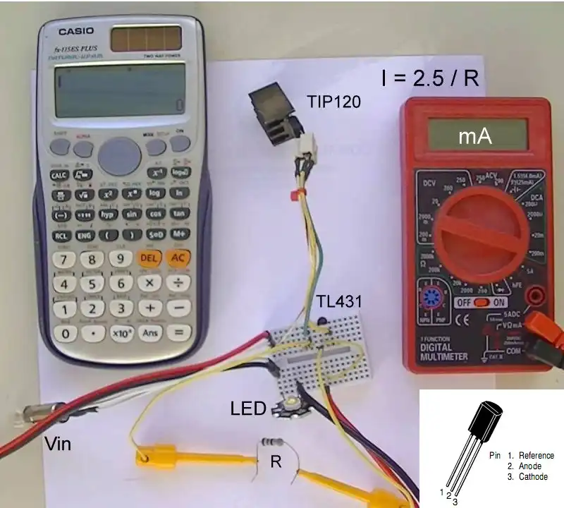
Fig. 2 TL431 power constant current source test setup.
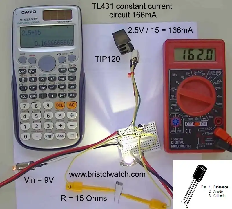
Fig. 3 TL431 power constant current source test with 15-Ohm resistor. Current = 166mA.
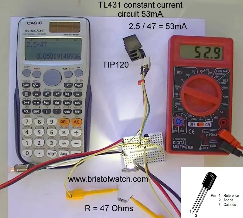
Fig. 4 TL431 power constant current source test with 47-Ohm resistor. Current = 53mA.
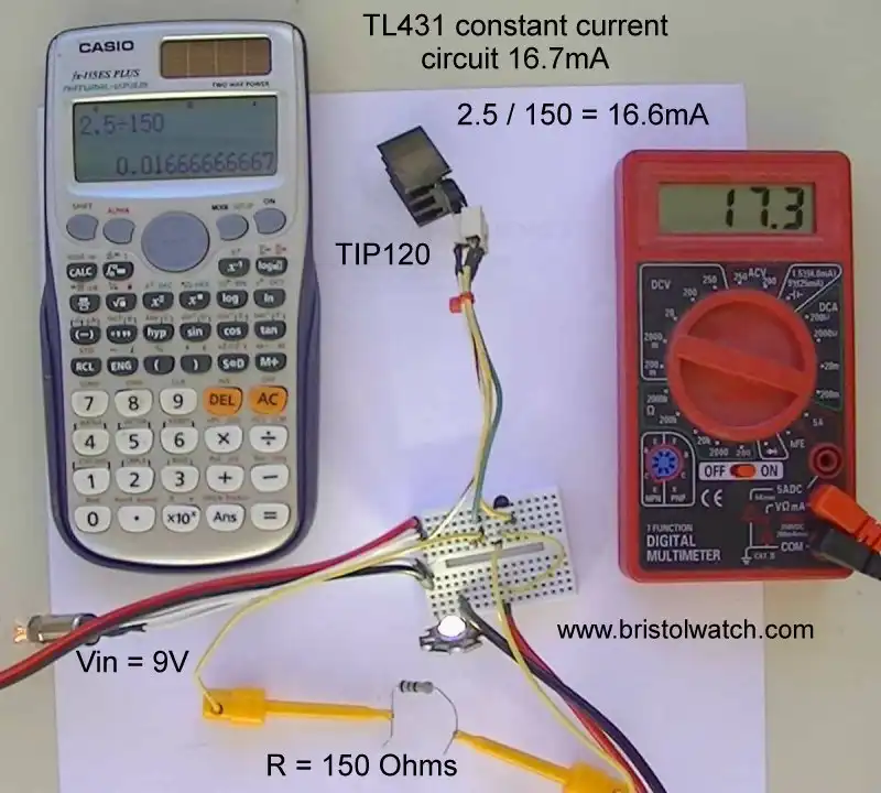
Fig. 5 TL431 power constant current source test with 15-Ohm resistor. Current ~17mA.
The current outputs closely follow the calculated values. A 10-Ohm resistor for R produced 250mA. A 5-Ohm for R started to reveal some problems. The TL431A is a low power device while the TIP120 Darlington is a much higher power device. This was stressing and starting to heat the TL431 above 400mA.
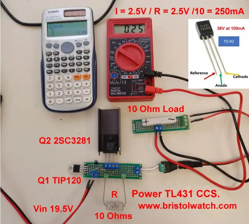
Fig. 6 TL431 power constant current source test setup 2.
Current Boost
A new test setup is shown above. The TL431A CCS circuit was built on a PC board. Screw block are used for power input, power output, for current set resistor R, and for an additional NPN transistor Q2. The original circuit above used the TL431A to drive a TIP120 Darlington power transistor. Now that TIP120 drives Q2 a higher power NPN pass transistor.
The input voltage is 19.5V and the test load of a 10-Ohm 10-watt resistor. A cheap Harbor Fright voltmeter measures the current.
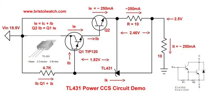
Fig. 7 TL431 constant current source power demo schematic.
For a larger image of above click tl431_power_ccs.jpg
The revised schematic is shown in Fig. 7. A 5-Ohm value for R produced 500mA as expected. A 2-Ohm value for R produced 1.136A. A 1-Ohm value for R produced only 2A max. I would limit R to no lower than 1.5-Ohms.
At 19.5V, ~2.5V is dropped across R, 2.5V across the 10-Ohm load. Then 14.5V is dropped across Q2. To cut down on wasted power reduce Vin from 19.5V to 10V.
While Q2 is a 2SC3281, it can be any NPN power transistor such 2N3055.
- Experiments with TL431 Shunt Regulator
- TL431A Precision Current Regulator Circuits
- TL431A Based Current Limiter Constant Current Source Circuits
- TL431A Shunt Regulator Circuits
- Using TL431A Li-Ion Battery Charger Tutorials
- TL431A Lithium-Ion Cell Charging Circuits
- Charging Multi-Cell Lithium-Ion Battery Packs
- TL431 Over-Voltage, Under-Voltage Detector Circuits
- TL431A Constant Current Source Working Circuits Demo
Related YouTube video TL431A Lithium-Ion Cell Charging Circuits
Related YouTube video TL431 Battery Charger Circuit Calculations Revised
Related YouTube video TL431 10-Volt Charger Short Version
Related YouTube video Charging, Charge-Balancing 18V Li-Ion Battery with TL431
Related YouTube video 18.5V Li-Ion Battery Charger with TL431 (short)
- Arduino Measures Current from Constant Current Source
- Constant Current Source Theory Testing
- Arduino Controlled Power Constant Current Source
- LM317 Adjustable Current Boost Power Supply
- Constant Current Circuits LM334, LM317
- Build LM317 0-34 Volt Power Supply
- LM334 Constant Current Source with Resistive Sensors
- LM317 High Power Constant Current Source Circuit
- LM317 Constant Current Source Circuits
- Test SCRs and Triacs
- Basic MOSFET Transistor Test Circuits
- High Voltage MOSFET Switching Circuits
- 3 Amp LM741 Op-Amp Constant Current Source
- Current Limiter Testing of Zener Diodes
- Current Limiter for Opto-Coupler Inputs
- LM317 CCS for Light Emitting Diodes
Other Circuits
- Hall Effect Magnetic Switches and Sensors
- Comparator Theory Circuits Tutorial
- ULN2003A Darlington Transistor Array with Circuit Examples
- Transistor-Zener Diode Regulator Circuits
- AC Power Supply Rectification
- Coils for Highly Selective Crystal Radio
- Neon (NE-2) Circuits You Can Build
- Photodiode Circuits Operation and Uses
- Photodiode Op-Amp Circuits Tutorial
Web site Copyright Lewis Loflin, All rights reserved.
If using this material on another site, please provide a link back to my site.