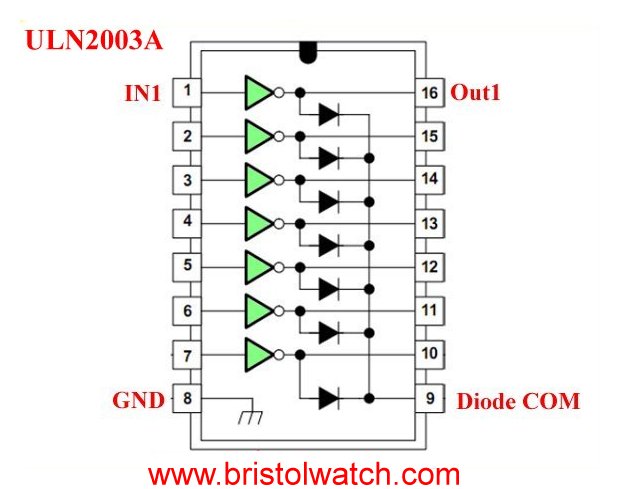
Figure 1 ULN2003A Darlington Transistor array internal block diagram.
How to Use the ULN2003A Darlington transistor Array with Examples
by Lewis Loflin
Here we will explore using the versatile ULN2003A Darlington Transistor array with a typical micro-controller such as Arduino.
The ULN2003A is a high-voltage, high-current Darlington transistor array consisting of seven NPN Darlington pairs that feature
high-voltage outputs with common-cathode clamp diodes for switching inductive loads.
The collector-current rating of a single Darlington pair is 500 mA.
The Darlington pairs can be paralleled for higher current capability. Applications include relay drivers, hammer drivers, lamp drivers, display drivers (LED and gas discharge), line drivers, and logic buffers.
Unipolar stepper motor driver using ULN2003 driving PNP Darlington transistors.
- Arduino Unipolar Stepper Motor Driver Board with Arduino Code video
- Arduino Power Magnetic Driver Board for Stepper Motors
Older video: ULN2003A Transistor Array with Arduino.
New video for 2024: ULN2003A Theory, Operation, Circuits
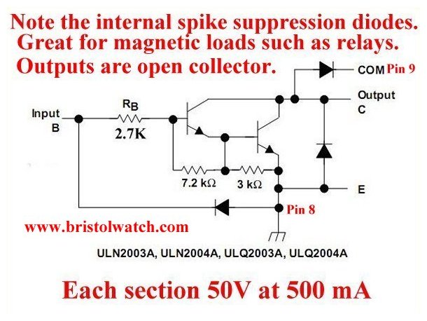
Figure 2
Internal diagram of the UNL2003A showing the open-collector Darlington configuration. The ULN2003A has a 2.7K ohm series base resistor for each Darlington pair for operation directly with TTL or 5-V CMOS devices.
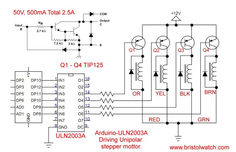
Figure 3a. ULN2003A driving a unipolar stepper motor.
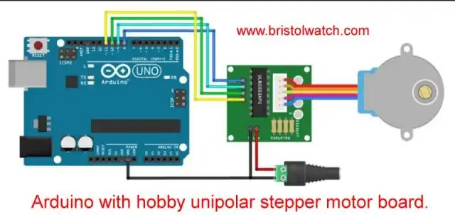
Figure 3b. ULN2003A driving a unipolar stepper motor directly with hobby board.
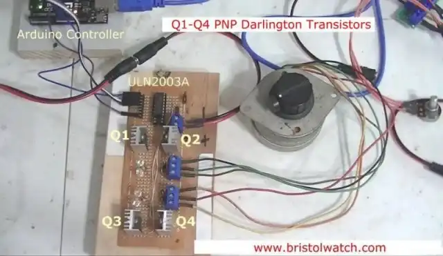
Figure 3c. ULN2003A driver board using TIP125 power Darlington transistors.
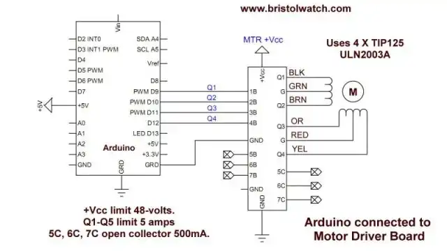
Figure 3d. ULN2003A driver board connected to an Arduino.
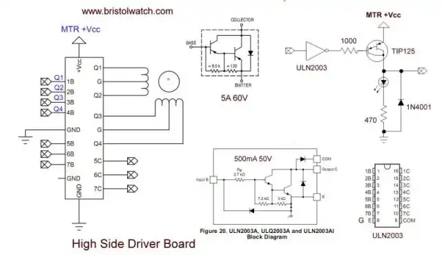
Figure 3e. ULN2003A driver board schematic and connection information..

Figure 4. ULN2003A driving 7, 24-volt light bulbs.

Figure 5. LN2003A driving 4 24-volt relays to control 4 120VAC lamps.
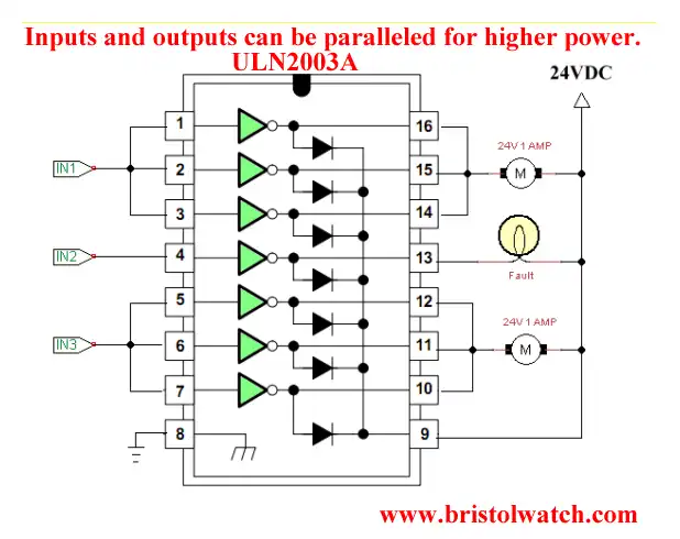
Figure 6. ULN2003A with parallel inputs-outputs driving 2 1-Amp motors.
I would not recommend using the above circuit. Use an actual transistor driver to handle higher currents. Never operate any device at maximum current or voltage. Derate to no more than 70%.
See Driving 2N3055-MJ2955 Power Transistors with Darlington Transistors.
![]()
- Quick navigation of this website:
- You Tube Channel
- Basic Electronics Learning and Projects
- Basic Solid State Component Projects
- Arduino Microcontroller Projects
- Raspberry Pi Electronics, Programming
- ULN2003A Darlington Transistor Array with Circuit Examples
- Tutorial Using TIP120 and TIP125 Power Darlington Transistors
- Driving 2N3055-MJ2955 Darlington Transistors
- Understanding Bipolar Transistor Switches
- N-Channel Power MOSFET Switching Tutorial
- P-Channel Power MOSFET Switch Tutorial
- H-Bridge Motor Control with Power MOSFETs
- Arduino Controlled IR2110 Based H-Bridge HV Motor Control
- IGBT Based High Voltage H-Bridge DC Motor Control
- More Power MOSFET H-Bridge Circuit Examples
- Build a High Power Transistor H-Bridge Motor Control
- Related:
- N-Channel Power MOSFET Switching Tutorial
- P-Channel Power MOSFET Switch Tutorial
- Test Power MOSFET Transistors, Observations
- Issues on Connecting MOSFETs in Parallel
- Basic MOSFET Transistor Test Circuits
- High Voltage MOSFET Switching Circuits
- Why Your MOSFET Transistors Get Hot YouTube
- Issues on Connecting MOSFETs in Parallel YouTube
- Simple Circuits for Testing MOSFET Transistors YouTube
See the following spec sheets:
- Basic Triacs and SCRs
- Constant Current Circuits with the LM334
- LM334 CCS Circuits with Thermistors, Photocells
- LM317 Constant Current Source Circuits
- TA8050P H-Bridge Motor Control
- All NPN Transistor H-Bridge Motor Control
- Basic Triacs and SCRs
- Comparator Theory Circuits Tutorial
Web site Copyright Lewis Loflin, All rights reserved.
If using this material on another site, please provide a link back to my site.