
Plate 1
P-Channel Power MOSFET Switch Tutorial
by Lewis Loflin
This tutorial will explore the use of a P-channel and N-channel MOSFETs as a power switch and general transistor theory. This switch will operate on the positive side of a power supply with a negative common. This is for use with 5-volt micro controllers such as Arduino.
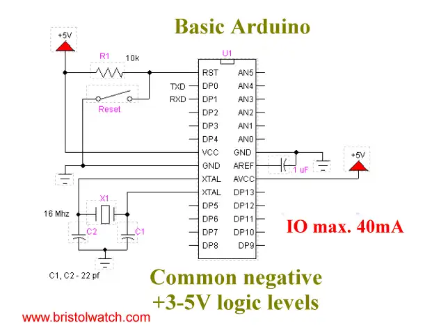
Plate 2
Pictured above is the basic electrical connections for Arduino and most modern micro-controllers. We have a negative common and a 5-volt Vcc. That dictates how we connect any driver transistor to the I/O pins. In addition each Arduino I/O pin can source/sink an absolute maximum of 40mA. (Note: operate at 20mA.)
First note that all MOSFETs are voltage operated devices and don't rely on a base current like a bipolar transistor. In many cases gate drive voltages below 5-volts won't work without a bipolar transistor switching in a higher voltage.
Update Dec. 2019. Many micro-controllers today are using 3.3-volt Vcc. This is also true of Raspberry Pi. I found two MOSFETs that work at 3.3-volts.
The IRFZ44N is an N-channel device rated at 55V and RDS(on) resistance of 0.032 Ohms max. The other is a P-channel device rated at 55V and a RDS(on) of 0.02 Ohms max.
Referring to Plate 1 whenever the voltage difference between the gate (G) and source (S) exceeds around 5-volts this opens a conductive channel between source (S) and drain (D) allowing current flow from the source back to the power supply. (Here we are using electron flow from negative to positive.)
This is often known as a series pass configuration.
Looking again at Plate 1 with no input to the base of Q1 the collector voltage rises to Vcc and with no difference in potential across Rgs Q6 and Q8 are turned off.
Applying 5-volts to the base resistors of Q8 and Q6 (plate 1) forward biases their base-emitter junctions allowing a small current flow Ib. Depending on the DC gain (hfe) of the individual transistors the base current is multiplied to produce Ic. The relationship is as follows:
Ie = Ib + Ic; Ib * hfe = Ic.
The base current Ib is determined by Vin - 0.6 / Rb. The 0.6 volts is the voltage drop across the BE junction. Let's say Q1 and Q7 are 2N2222As that have minimum hfe of 90 and we desire an Ic of 20 mA. Here is how this will work:
   Ib = Ic / hfe;
   Ib = 20mA / 90;
   Ib =~ 220uA

   Rb = Vin - 0.6 / Ib
   Rb = 5 - 0.6 / 220uA
   Rb = 20K
Now some issues on switching transistors. We want them operating in their saturation mode where any additional base current will produce no increase in collector current (Ic). When making these calculations a transistor spec sheet gives a range for hfe, assume the lowest value. Next as long as we don't exceed the max base current rating assume extra current. In this case I would use a 2.2K for Rb.
When a bipolar transistor is operating at saturation the emitter-collector voltage equals 0.5V. In the case of MOSFETs Q6 and Q8 we want those operating in saturation mode as well. With a 12-volt difference between gate-source this assures a fast, hard turn on. At saturation MOSFETs such as the IRF630 and IRF9630 have a drain-source resistance of 0.4 and 0.8 ohms respectively.
So Let's find Rgs where we want to drop 11.5 volts:
   Rgs = 11.5 / Ic
   Rgs = 11.5 / 20mA
   Rgs = 575 ohms.
Let's assume a much higher value of say 10K to assure the desired voltage drop. Again we have lots of room to play with to assure saturation of all four transistors. Note that in reality Rgs sets the current level when Q1 and Q7 are in saturation mode.
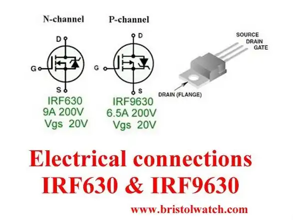
Plate 3
MOSFET Gate-Source Breakdown
One final issue is the gate-source breakdown voltage of both MOSFETs or Vgs. For the IRF630 and IRF9630 this is 20 volts. The 24-volts in Fig. A would damage Q8. The 10-volt Zener in series with Q7's collector will keep this within a safe margin.
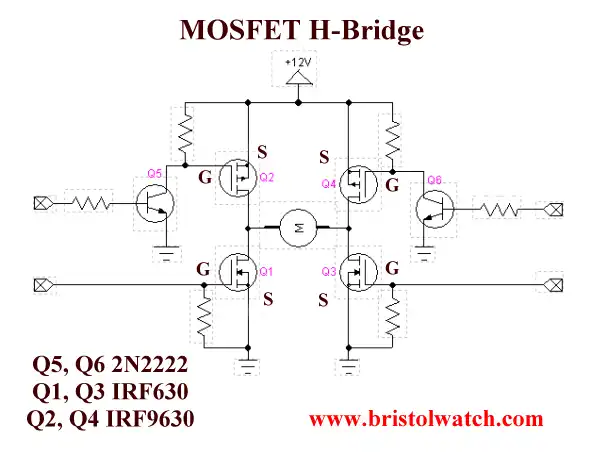
Plate 4
Uses
There are number of advantages to the above circuits. A low source-drain turn on resistance means more power is delivered to the load and less heating of series pass MOSFETs. The ability to operate at 5-volts makes direct connections to a micro-controller a cinch. In addition this can be pulse-width-modulated to control motor speed on a say H-bridge circuit.
The largest use of these circuits is H-bridge motor controls. They are used in conjunction with N-channel MOSFET switches.
Note that Rg (or Rgs) is used to bleed the charges off the MOSFET gates or else they may not turn off.
Have fun.
I hope the series was helpful. Any corrections, suggestions etc. e-mail me at lewis@bvu.net.
![]()
- Quick navigation of this website:
- You Tube Channel
- Basic Electronics Learning and Projects
- Basic Solid State Component Projects
- Arduino Microcontroller Projects
- Raspberry Pi Electronics, Programming
- ULN2003A Darlington Transistor Array with Circuit Examples
- Tutorial Using TIP120 and TIP125 Power Darlington Transistors
- Driving 2N3055-MJ2955 Darlington Transistors
- Understanding Bipolar Transistor Switches
- N-Channel Power MOSFET Switching Tutorial
- P-Channel Power MOSFET Switch Tutorial
- H-Bridge Motor Control with Power MOSFETs
- Arduino Controlled IR2110 Based H-Bridge HV Motor Control
- IGBT Based High Voltage H-Bridge DC Motor Control
- More Power MOSFET H-Bridge Circuit Examples
- Build a High Power Transistor H-Bridge Motor Control
- Related:
- N-Channel Power MOSFET Switching Tutorial
- P-Channel Power MOSFET Switch Tutorial
- Test Power MOSFET Transistors, Observations
- Issues on Connecting MOSFETs in Parallel
- Basic MOSFET Transistor Test Circuits
- High Voltage MOSFET Switching Circuits
- Why Your MOSFET Transistors Get Hot YouTube
- Issues on Connecting MOSFETs in Parallel YouTube
- Simple Circuits for Testing MOSFET Transistors YouTube
See the following spec sheets:
- Basic Triacs and SCRs
- Constant Current Circuits with the LM334
- LM334 CCS Circuits with Thermistors, Photocells
- LM317 Constant Current Source Circuits
- TA8050P H-Bridge Motor Control
- All NPN Transistor H-Bridge Motor Control
- Basic Triacs and SCRs
- Comparator Theory Circuits Tutorial
Web site Copyright Lewis Loflin, All rights reserved.
If using this material on another site, please provide a link back to my site.