Fig. 1
LM334, LM317, TL431 Constant Current Circuits
by Lewis Loflin
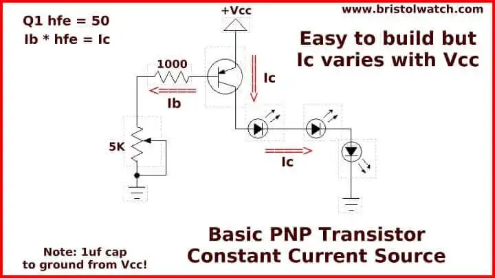
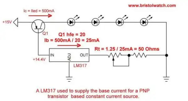
A constant current source (CCS) in electronics is a device/circuit that produces a constant value of current regardless of source voltage or load resistance. Fig. 1 illustrates a simple constant current source (CCS) circuit using a PNP bipolar transistor.
The values of the Ic = Ib × Hfe (Beta) of the transistor. A constant current circuit can also be used as a current limiter.
Ic is collector-emitter current, Ib is base-emitter current, and Hfe is the DC gain of the transistor.
The above circuit suffers one weakness, current will drift with transistor temperature changes.
Maxim Semiconductor notes the following on why we need to use a constant current source:
When applying white LEDs for display back lighting or other illumination applications, there are two reasons to drive them with constant current: To avoid violating the Absolute Maximum Current Rating and compromising the reliability.
To obtain predictable and matched luminous intensity and chromaticity from each LED...The forward current vs. forward voltage of six random white LEDs (three from each of two manufacturers) ... driving these six LEDs with 3.4V, for instance, will cause their forward current to vary from 10mA to 44mA, depending upon the LED."
Besides LEDs constant current sources are used with resistive sensors such as photocells and thermistors for greater stability and for current limited power supplies. Also useful for testing and prototyping.
See LM334 Constant Current Source with Resistive Sensors.
- Current Limiter Allows Safe Testing of Zener Diodes, LEDs
- Current Limiter Circuits for Opto-Coupler Input LEDs
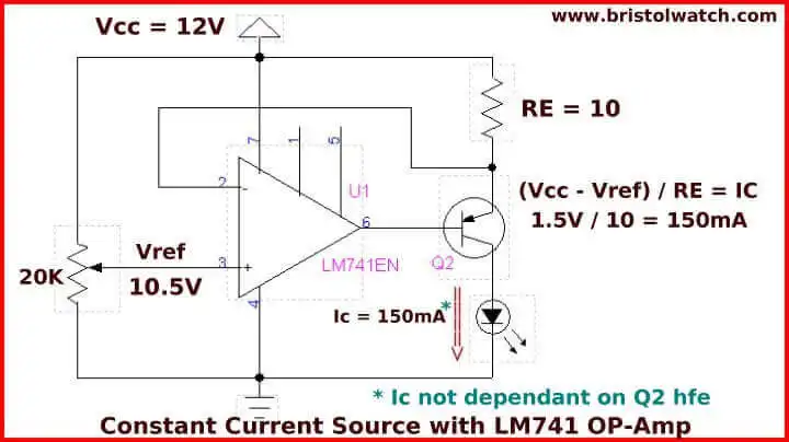
Fig. 2
Fig 2 illustrates a constant current source with a 741 op amp. See 3 Amp LM741 Op-Amp Constant Current Source.
In Fig. 1 Ib is controlled by a 1K resistor and a 5K potentiometer. With a VCC of 12-volts, we drop 0.6 volts across the base-emitter junction of Q1. We adjust the potentiometer for a base current of 3mA (.003 Amps.) If Q1 has a hfe of 50: Ic = 0.003 × 50 = 150mA or 0.15A.
These circuits are a must for operating high-power light emitting diode (LED) arrays. The circuit above is simple, can be a little unstable due to temperature drift with Q1 causing the current drift. That problem is minor compared to power supply drift can cause far greater instability.
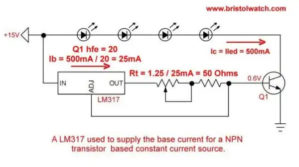
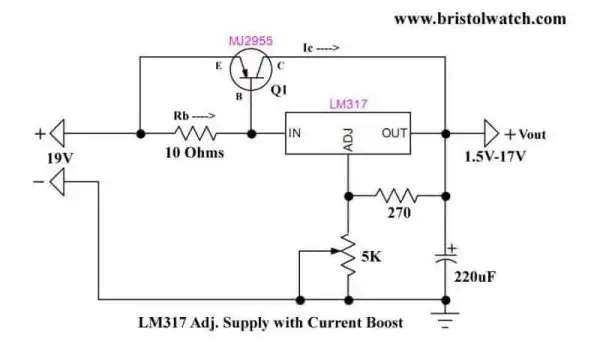
Other constant current sources use the LM317 a popular variable voltage regulator.
- LM317 Adjustable Voltage current Boost Power Supply
- LM317 High Power Constant Current Source Circuit
- LM317 Constant Current Source Circuits
The TL431A is another popular part in a small TO-92 package. In simple terms the TL431A acts a temperature compensated variable/adjustable Zener diode.
It can also act as a voltage reference or constant current source.
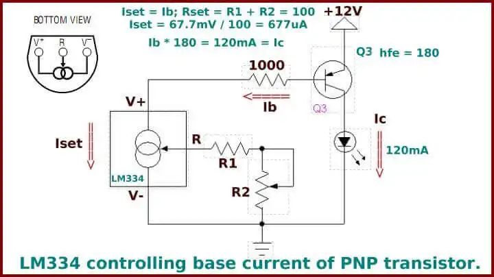
Fig. 3
Fig 3 uses a LM334 a three-terminal current source designed to operate at current levels from 1uA to 10mA as set by an external resistor Rset. The device operates as "a true two-terminal current source, requiring no extra power connections." It can also operate as a temperature sensor.
In this example I'm using the LM334 to control Ib on Q3. Rset is the R1 and R2 combination adjusted for 100 ohms. Iset = Ib = 67.7mV / Rset = 677uA. Ic = Ib * hfe; Ic = 677uA * 180 = 120mA. Q3 was a 2N2907. See LM334 Spec sheet.
This is far superior to the two earlier circuits because power supply swings produced little measurable change in Ic. But the LM334 suffers from a maximum drive current of only 10mA and there are many applications where far higher currents are need.
In our next section we explore using the LM317 variable voltage regulator in its constant current source mode.
See LM317 Constant Current Circuits
- Arduino Measures Current from Constant Current Source
- Constant Current Source Theory Testing
- Arduino Controlled Power Constant Current Source
- LM317 Adjustable Voltage, Current Boost Power Supply
- Constant Current Circuits LM334, LM317
- Build LM317 0-34 Volt Power Supply
- LM334 Constant Current Source with Resistive Sensors
- LM317 High Power Constant Current Source Circuit
- LM317 Constant Current Source Circuits
- Test SCRs and Triacs
- Basic MOSFET Transistor Test Circuits
- High Voltage MOSFET Switching Circuits
- 3 Amp LM741 Op-Amp Constant Current Source
- Current Limiter Testing of Zener Diodes
- Current Limiter for Opto-Coupler Inputs
- LM317 CCS for Light Emitting Diodes
- Experiments with TL431 Shunt Regulator
- TL431A Precision Current Regulator Circuits
- TL431A Based Current Limiter Constant Current Source Circuits
- TL431A Shunt Regulator Circuits
- Using TL431A Li-Ion Battery Charger Tutorials
- TL431A Lithium-Ion Cell Charging Circuits
- Charging Multi-Cell Lithium-Ion Battery Packs
- TL431 Over-Voltage, Under-Voltage Detector Circuits
- TL431A Constant Current Source Working Circuits Demo
Related YouTube video TL431A Lithium-Ion Cell Charging Circuits
Related YouTube video TL431 Battery Charger Circuit Calculations Revised
Related YouTube video TL431 10-Volt Charger Short Version
Related YouTube video Charging, Charge-Balancing 18V Li-Ion Battery with TL431
Related YouTube video 18.5V Li-Ion Battery Charger with TL431 (short)
- Arduino Measures Current from Constant Current Source
- Constant Current Source Theory Testing
- Arduino Controlled Power Constant Current Source
You Tube Videos
- Adjustable LM317 High Power Current Source
- Current Boost LM317 Adj. Power Supply
- LM317 Constant Current Source Circuits
Other Circuits
- Hall Effect Magnetic Switches and Sensors
- Comparator Theory Circuits Tutorial
- ULN2003A Darlington Transistor Array with Circuit Examples
- Transistor-Zener Diode Regulator Circuits
- AC Power Supply Rectification
- Coils for Highly Selective Crystal Radio
- Neon (NE-2) Circuits You Can Build
- Photodiode Circuits Operation and Uses
- Photodiode Op-Amp Circuits Tutorial
Web site Copyright Lewis Loflin, All rights reserved.
If using this material on another site, please provide a link back to my site.