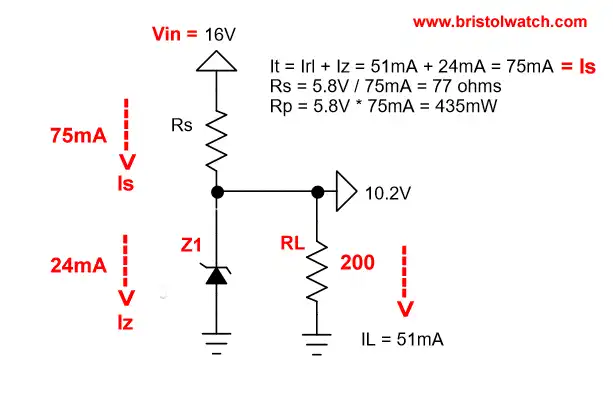
Fig. 1 Typical Zener diode circuit.
Transistor-Zener Diode Regulator Circuits
by Lewis Loflin
Updated, revised October 2016. This will explore the basic operation of Zener diodes and their use as voltage regulators. They will be used in conjunction with common bi-polar transistors to boost the output current and can used for real-world voltage regulators by students and hobbyists.
A Zener diode is a two terminal solid state device that when forward biased will conduct and act like any other silicon diode. Zener diodes are always used in there reverse bias mode designed to breakdown at a particular voltage. Fig.1 illustrates a basic Zener diode connection.
Z1 and RS are in series while a 200 Ohm load resistor RL is parallel to Z1. Our total current (Is) flows through RS and divides through Z1 (24mA) and RL (51mA). Z1 at 10.2 volts maintains a steady voltage across RL as the Vin varies over a particular range.
If Vin drops to 14 volts the Zener current Iz drops to maintain the voltage on RL. If Vin increases to say 18 volts, then the Zener current Iz increases maintaining the voltage across RL.
At all times the voltage drop across Z1 plus RS always equals the supply voltage Vin, while the voltage across RL thus IL is constant. If RS is too small excessive current will overheat Z1.
If RS is too large then we lack the minimum current Iz to maintain voltage regulation. Note the following:
Is = Iz + IL = 24mA + 51mA = 75mA;
RS = VRs / Is = 5.8V / 75mA = 77 Ohms.
The next question becomes, just how much current can this circuit provide to a load? Let's look at the problem.
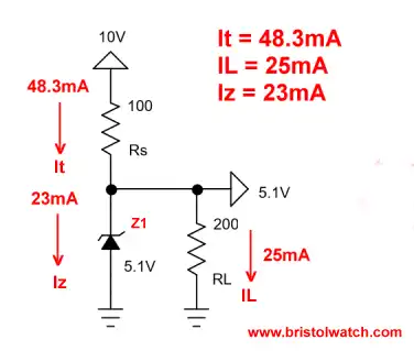
Fig.2
In Fig. 2 we have a properly operating Zener diode regulation circuit at Z1 = 5.1 volts with a 10-volt supply. But what happens of we increase the load from RL? Note that to work properly we must maintain a minimum value of Iz.
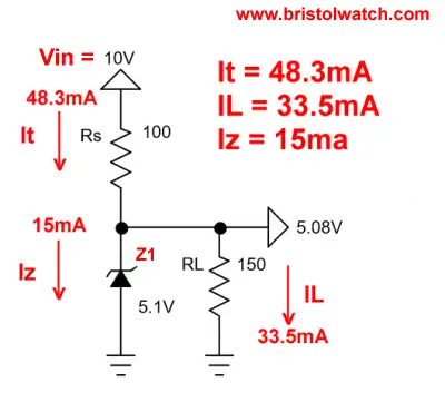
Fig. 3
In Fig. 3 we dropped RL from 200 Ohms to 150 Ohms increasing IL. While total current though RS remains the same, part of the current for Z1 (Iz) goes to RL and we are on the edge of no voltage regulation.
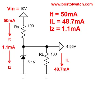
Fig. 4
In Fig. 4 RL is now 100 ohms and has taken so much current from Z1 we no longer have any voltage regulation at all. This setup is almost worthless as a power supply in itself except at low currents. That is why we use transistors in conjunction with Zener diodes.
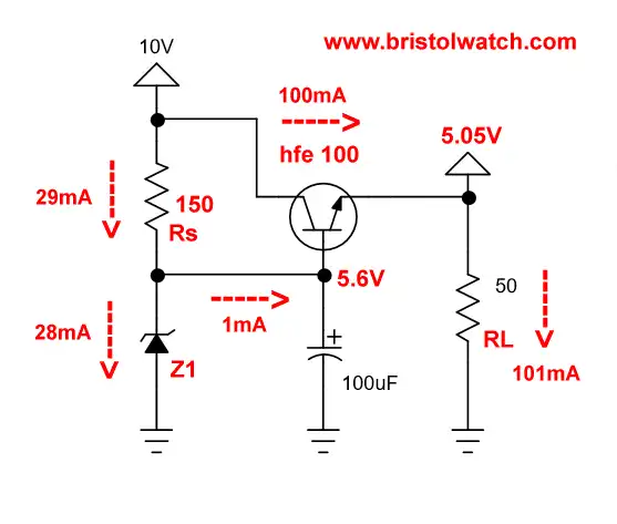
Fig. 5
To get around the power limitations we use a series-pass transistor. In Fig. 5 a NPN transistor with a Hfe or DC gain of 100 in effect "multiplies" 1mA from the Zener-resistor circuit to 100mA.
The reason I went to a 5.6 volt Zener is to compensate for the 0.6V drop across the B-E junction of Q1. Yes you need the 100uF capacitor to assure power supply ripple doesn't cause problems. As we draw more load current 99% of the current originates with Q1.
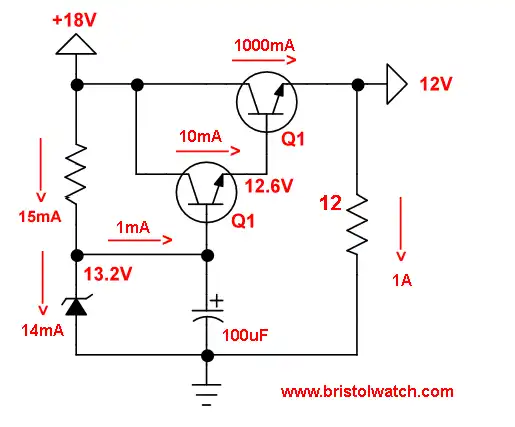
Fig. 6
In Fig. 6 we use two NPN transistors in a Darlington configuration to boost current output to 1 amp through a 12 Ohm load. I had to go to a 13.2 volt Zener to make up for the voltage drops across the two B-E junctions.
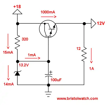
Fig. 7
In Fig. 7 we use a Darlington to boost current output to 1 amp through a 12 Ohm load.
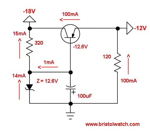
Fig. 8
In Fig. 8 we have a Zener diode regulator for a negative polarity power supply. The NPN transistor was replaced with a PNP transistor, and the polarity of the Zener diode and 100uF capacitor were reversed. All current flows were also revered.
That completes this introduction to Zener diode based voltage regulation.
Related - Experiments with TL431A Shunt Regulator a type of variable Zener diode.
YouTube video: Zener Diode Tutorial.
![]()
- Quick navigation of this website:
- You Tube Channel
- Basic Electronics Learning and Projects
- Basic Solid State Component Projects
- Arduino Microcontroller Projects
- Raspberry Pi Electronics, Programming
- Build Autotransformer-Variac AC and DC Power Supply
- Connecting Transformers in Series-Parallel
- Build an Adjustable 0-34 volt power supply with the LM317
- AC Power Supply Rectification
- Basic Power Transformers
- Transistor-Zener Diode Regulator Circuits
- Tips for the LM78XX Series Voltage Regulators
- Bi-Polar Power Supplies
- Connecting Series-Parallel Batteries
- ULN2003A Darlington Transistor Array with Circuit Examples
- Tutorial Using TIP120 and TIP125 Power Darlington Transistors
- Driving 2N3055-MJ2955 Darlington Transistors
- Understanding Bipolar Transistor Switches
- N-Channel Power MOSFET Switching Tutorial
- P-Channel Power MOSFET Switch Tutorial
- H-Bridge Motor Control with Power MOSFETs
- Arduino Controlled IR2110 Based H-Bridge HV Motor Control
- IGBT Based High Voltage H-Bridge DC Motor Control
- More Power MOSFET H-Bridge Circuit Examples
- Build a High Power Transistor H-Bridge Motor Control
- Basic Triacs and SCRs
- Constant Current Circuits with the LM334
- LM334 CCS Circuits with Thermistors, Photocells
- LM317 Constant Current Source Circuits
- TA8050P H-Bridge Motor Control
- All NPN Transistor H-Bridge Motor Control
- Basic Triacs and SCRs
- Comparator Theory Circuits Tutorial
Web site Copyright Lewis Loflin, All rights reserved.
If using this material on another site, please provide a link back to my site.