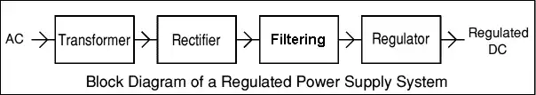
Figure 1
Using LM78XX Series Voltage Regulators Tutorial
by Lewis Loflin
In this section we will explore fixed, regulated power supplies. We will make use of the 78XX and 79XX series of voltage regulators. They are made by several manufacturers, most are readily available, and are inexpensive. In Basic Power Supply Rectification Tutorial we already discussed the process from AC in to filtering. Later we will examine adjustable, regulated power supplies.
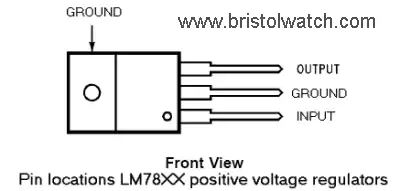
Figure 2
The LM78XX series of three terminal positive regulators are available in the TO-220 package. Each type employs internal current limiting, thermal shut down and safe operating area protection, making it essentially indestructible. If adequate heat sinking is provided, they can deliver over 1A output current. These devices can be used with external components to obtain adjustable voltages and currents. Available output voltages: 5, 6, 8, 9, 10, 12, 15, 18, and 24V. Figure 2 shows the electrical connection for the LM78XX series.
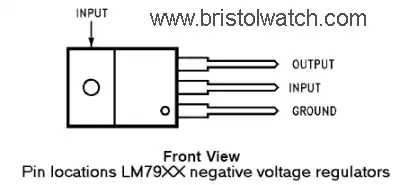
Figure 3
The LM79XX series of 3-terminal regulators is available with fixed output voltages of -5V, -12V, and -15V. These devices need only a compensation capacitor (1uF solid tantalum or 25uF aluminum electrolytic) at the output.
The LM79XX series is packaged in the TO-220 power package and is capable of supplying 1.5A of output current with proper heat sinking. Like the LM78XX series they hey employ internal current limiting safe area protection and thermal shutdown for protection against virtually all overload conditions. Figure 3 shows the electrical connections on the LM79XX series and how they differ from the LM78XX series.
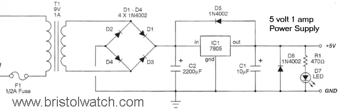
Figure 4
Figure 4 shows a basic 5 volt general purpose power supply. Any of the other positive regulators will work the same way as long as one observes proper input voltage levels and component ratings.
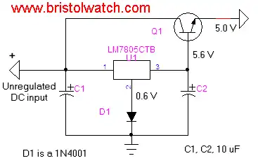
Figure 5
In figure 5 we have added a NPN pass transistor such as a 2N3055 to boost output current to several amps. Diode D1 was added to compensate for the voltage drop across the base-emitter junction of Q1.
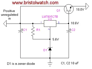
Figure 6
In figure 6 we have added a 5.6 volt Zener diode for D1. By using Zeners we can produce any number of odd voltage requirements. Q1 works the same as in figure 5 or could be left out and a 5 volt Zener used if current requirement is under 1 amp.
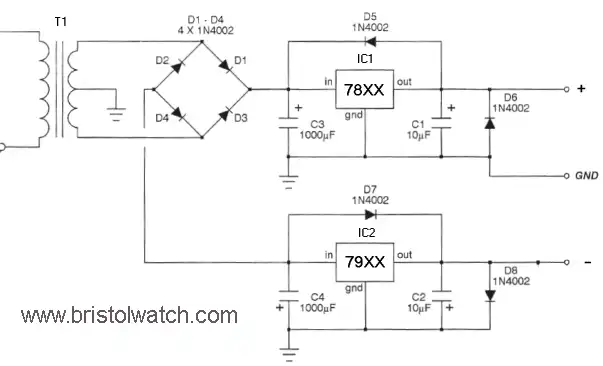
Figure 7
Figure 7 illustrates a regulated bi-polar power supply for use with OP-AMP circuits.
![]()
- Quick navigation of this website:
- You Tube Channel
- Basic Electronics Learning and Projects
- Basic Solid State Component Projects
- Arduino Microcontroller Projects
- Raspberry Pi Electronics, Programming
- Build Autotransformer-Variac AC and DC Power Supply
- Connecting Transformers in Series-Parallel
- Connecting Series-Parallel Batteries
- Connecting Transformers in Series-Parallel
- Build an Adjustable 0-34 volt power supply with the LM317
- AC Power Supply Rectification
- Basic Power Transformers
- Transistor-Zener Diode Regulator Circuits
- Tips for the LM78XX Series Voltage Regulators
- Bi-Polar Power Supplies
Related videos:
Basic Electronic Power Supplies Part 1
Basic Electronic Power Supplies Part 2
Build a low voltage DC power supply Part 3
AC Power Lab on Series Circuits Part 1
AC Power Lab on Series Circuits Part 2
- Photo Detector Devices:
- Photodiode Circuits Operation and Uses
- Photodiode Op-Amp Circuits Tutorial
- Photo Voltaic Tutorial MOSFET Output Solid State Relays
- Transistor Driver Circuits
- Opto-Isolated Transistor Drivers for Micro-Controllers
- MOSFET Transistors, IGBTs Observations
- Added Nov. 16, 2014
- ULN2003A Darlington Transistor Array with Circuit Examples
- Tutorial Using TIP120 and TIP125 Power Darlington Transistors
- Driving 2N3055-MJ2955 Power Transistors with Darlington Transistors
- Understanding Bipolar Transistor Switches
- N-Channel Power MOSFET Switching Tutorial
- P-Channel Power MOSFET Switch Tutorial
- More Power MOSFET H-Bridge Circuit Examples
- Build a High Power Transistor H-Bridge Motor Control
Web site Copyright Lewis Loflin, All rights reserved.
If using this material on another site, please provide a link back to my site.