Figure 1
Bipolar Power Supplies
by Lewis Loflin
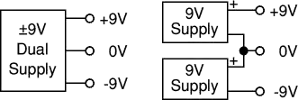
In figure 1 we have an example of a bi-polar power supply using two 9-volt batteries. They share a common ground and the output can be any combination of polarities or voltages. For example the ATX power supplies used in most PCs today have multiple voltage outputs, but share one common. In the ATX supply we have plus and minus 5 volts, plus and minus 12, and three volts.
Besides their use in home PCs, bipolar supplies are used in many OP-AMP circuits and high power audio amplifiers.
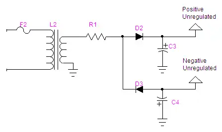
Figure 2
In figure 2 we have constructed a bi-polar power supply using a 12.6 volt transformer. D2 charges up C3 on the positive half-cycle, while D3 charges up C4 during the negative half-cycle. In both cases the output voltage would be 17.8 volts. (12.6 * 1.414.) The polarities would be opposite in regards to ground.
The same rules for half-wave rectification for both polarities still holds true. Because capacitors C3 and C4 would have to large (at least 3300 uF), R1 limits the inrush of current when power is applied. The values is usually 1-10 ohms at 5 watts.
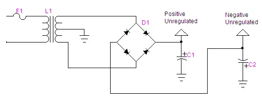
Figure 3
Figure 3 illustrates a bi-polar supply using a diode bridge and the transformer center tap as common. The same rules apply as before with the voltage at half while the current is doubled. This is full-wave rectification and can use smaller capacitors than those in figure 7 for the same load.
If we use a 25.5 volt 3 amp transformer each output voltage will be 25.2/2 * 1.414 or 17.8 volts.
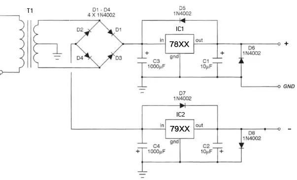
Figure 4
Figure 4 illustrates a regulated bi-polar power supply for use with OP-AMP circuits.
![]()
- Quick navigation of this website:
- You Tube Channel
- Basic Electronics Learning and Projects
- Basic Solid State Component Projects
- Arduino Microcontroller Projects
- Raspberry Pi Electronics, Programming
- Build Autotransformer-Variac AC and DC Power Supply
- Connecting Transformers in Series-Parallel
- Build an Adjustable 0-34 volt power supply with the LM317
- AC Power Supply Rectification
- Basic Power Transformers
- Transistor-Zener Diode Regulator Circuits
- Tips for the LM78XX Series Voltage Regulators
- Bi-Polar Power Supplies
- Connecting Series-Parallel Batteries
Opto-Coupler SCR and Triac Circuits
SCRs and Triacs are used to control AC and DC power systems. With a microcontroller such as Arduino using a zero-crossing can control AC power to control light levels, AC motor speed, and resistive heating elements..
- Basic Triacs and SCRs
- Solid State AC Relays with Triacs
- Diac Waveform Generator, Trigger Circuits
- SIDAC Operation and Trigger Circuits
- Light Activated Silicon Controlled Rectifier (LASCR)
- Light Activated SCR Based Optocouplers Circuit Examples
- Comparing Photo Triac, Photo SCR Opto-Couplers
- Silicon Controlled Rectifier Review and Circuits
- Silicon Controlled Rectifiers Connected as Power Triacs
- Simple Triac-SCR Test Lab for You Tube
- AC Zero Crossing Detectors for Arduino
- Zero-Crossing Detectors Circuits
- Hardware Interrupts Demo and Tutorial for Arduino
- In Depth Look at AC Power Control with Arduino
- Arduino AC Power Control Using Interrupts
Web site Copyright Lewis Loflin, All rights reserved.
If using this material on another site, please provide a link back to my site.