In Depth Look at AC Power Control with Arduino
by Lewis Loflin
Watch the related YouTube Video
In the above video and the code below we take an in depth look at the hardware for using Arduino interrupts to control AC power through a triac. Using a zero-crossing detector Arduino will detect the pulse then calculate a delay to control the power output to a load. The complete circuit schematic.
For more on basic AC voltage see my video Basic Electronic Power Supplies
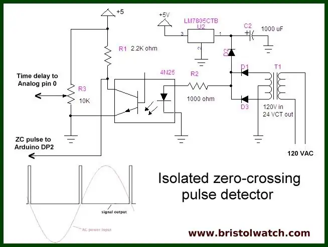
Fig. 2
Fig. 2 shows the 5-volt power supply for Arduino but includes blocking diode D2. On the cathode side we have filtered DC which is regulated to 5-volts through U2. On the Anode side we have unfiltered raw 120 Hz DC going to the LED in the 4N25 opto-coupler. The output from the photo-transistor collector goes to digital pin 2 of Arduino to interrupt 0. Potentiometer R3 goes analog pin 0 and is used to calculate the time delay for the half-cycle triac firing pulses.
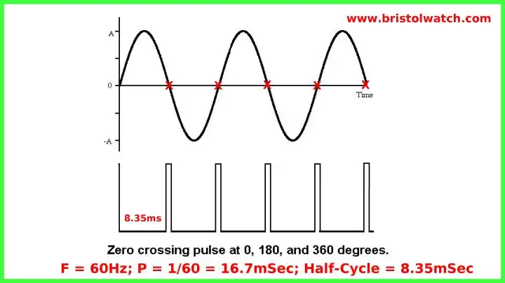
The figure above shows the relationship of the zero-crossing pulse with the AC sine wave. By detecting the pulse and programming a delay one can control the power output level to a AC load.
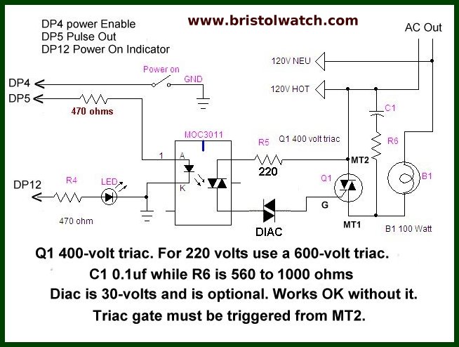
Fig. 3
Fig 3 shows the triac firing circuit. The MOC3011 opto-coupler uses a photo triac as opposed to a transistor. Pulses synchronized to the AC sinewave half-cycle are output from Arduino digital pin 5 to the LED in the MOC3011, which also serves to isolate the high voltage AC from the low-voltage components.
Pressing the power switch will enable trigger pulses to the MOC3011 while the LED on digital pin 12 is a power on indicator. C1 and R6 form a snubber circuit for inductive loads. Without a snubber switching noise from inductive loads will cause miss-firing of the triac.
Note that on 60Hz power lines a half cycle is 8.35mSec. while a 50Hz system is 10mSec. Adjust the half-cycle time-delay for 50Hz.
/*
Purpose: to detect zero crossing pulse at
 INT0 digital pin 2, which after delay
 switches on  a triac.
 Power output to triac activated by external switch.
 */

#define triacPulse 5
#define SW 4
#define aconLed 12

int val;

void setup()  {
  pinMode(2, INPUT);
  digitalWrite(2, HIGH); // pull up
  pinMode(triacPulse, OUTPUT);
  pinMode(SW, INPUT);
  digitalWrite(SW, HIGH);
  pinMode(aconLed, OUTPUT);
  digitalWrite(aconLed, LOW);
}

void loop() {
  // check for SW closed
  if (!digitalRead(SW))   {
    // enable power
    attachInterrupt(0, acon, FALLING);
    // HV indicator on
    digitalWrite(aconLed, HIGH);
  }  // end if
  else if (digitalRead(SW)) {
    detachInterrupt(0); // disable power
    // HV indicator off
    digitalWrite(aconLed, LOW);
  }  // else
} // end loop


// begin AC interrupt routine
// delay() will not work!
void acon()
{
  delayMicroseconds((analogRead(0) * 6) + 1000); // read AD1
  digitalWrite(triacPulse, HIGH);
  delayMicroseconds(200);
  // delay 200 uSec on output pulse to turn on triac
  digitalWrite(triacPulse, LOW);
}
- Quick navigation of this website:
- Basic Electronics Learning and Projects
- Basic Solid State Component Projects
- Arduino Microcontroller Projects
- Raspberry Pi Electronics, Programming
Stepper Motors
- Easy Driver Micro-Stepper Controller to Arduino
- Unipolar Stepper Motor with a Arduino
- Considerations for Using Stepper Motors
- Connecting the Arduino to a L298N H-Bridge
- L298N Motor Controller Theory and Projects
- TA8050 H-Bridge Motor Controller
- Battery Charger related:
- Solar Panel Charge Controller Using Arduino
- Solar Panel Battery Charge Controller Using Arduino
- Solar Panel Battery Charge Controller Switching Circuit
- Arduino AC Power Control Tutorial
- Rotary Encoder Using Arduino Hardware Interrupts
- Arduino Controlling 74C164 Shift Register
- Arduino Interface MC3479 Stepper Motor Controller
Serial LCD Display and assorted Sensors
- Arduino LCD Display using 74164 Shift Register
- Arduino LCD Display with DS18B20
- Arduino LCD Display with DHT11 Sensor
- Arduino with MM5451 LED Display Driver
- Arduino MAX7219 Operates 8X8 LED Matrix
- Arduino RTC Clock MAX7219 LED Display
- BCD Conversion with MAX7219
- Hatching Chicken Eggs with Arduino
- Arduino TMP37 Temperature Sensor
- Arduino TMP37 Temperature Sensor Tutorial
- Testing the Keyes IR Sensor Module with Arduino
- Arduino to MCP23016, LCD Display
- Time-Date with Arduino, LCD Display, DS1307 RTC
- Controlling Driveway Lights with the Arduino
- TSL230R Light to Frequency Converter
- Arduino with MCP23016 I/O Expander
- Arduino DS1307 Real Time Clock
- Arduino with 24LC08 Serial EEPROM
- MC3479 Stepper Motor Controller with Arduino
Web site Copyright Lewis Loflin, All rights reserved.
If using this material on another site, please provide a link back to my site.