Arduino Controlling Low-Voltage Driveway Lights
by Lewis Loflin
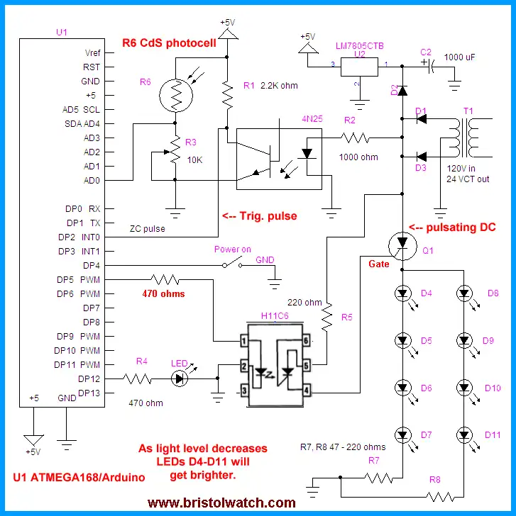
In this circuit we demonstrate how to use SCRs to control low-voltage pulsating DC to operate homemade LED light panels. While in this circuit I use the Arduino, the concepts should work with any number of micro-controllers using either hardware interrupts or polling. We must use pulsating DC or the SCR won't operate properly. See Basic SCRs/Triacs.
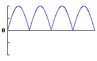
Full wave pulsating DC.
In the main circuit diagram above transformer T1, D1, and D3 produce a positive going pulsating DC with a peak voltage of about 18 volts and a frequency of 120 Hertz. Diode D2 blocks the filtering effect of capacitor C2, which with U2 supplies positive five volts for the microcontroller. See Basic AC Rectification and Filtering
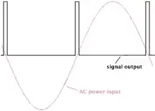
Zero crossing pulse from 4N25 in relation to AC sine wave.
The 4N25 opto-coupler provides a narrow 120 Hertz pulse at zero and 180 degrees of the sine wave. This pulse is fed to digital pin 2 (Dp2) of the controller to trigger an interrupt when the sine wave passes zero and 180 degrees. (There's 360 degrees in a sine wave.) See 4N25 Opto-Coupler (PDF file)
This illustrates to process with full-wave unfiltered D.C.
CdS photocell R6 and R3 form a voltage divider. As light intensity increases the resistance of R6 decreases causing the voltage to rise at the junction of R3, R6, and analog to digital converter pin Ad0 on the controller. (R3 can be a 10k resistor, which is what I used.) When read by the program this 10-bit AD converter will produce a value between 0 and 1023. This value is used in a delay routine to determines the firing point of the SCR. The longer the delay, the less power to the LED strings and less light output. See Using a CdS Photocells
When the power on switch is pressed at Dp4 a 100 uSec. positive-going pulse is sent to the H11C6 opto-coupler through a 470 ohm resistor. This in turn fires the SCR at the desired time during the delay time 120 times per second. The H11C6 contains a LED light source used to fire the light activated silicon-controlled rectifier (LASCR) in order to fire the main power SCR Q1. R5 limits the gate current of Q1 while R7 and R8 limit the current in the LED strings. See H11C6 spec sheet. (PDF file)
The LED strings are composed of four high intensity white LEDs in series. At 3 to 3.5 volts each four in series operate at 12-14 volts. Q1 used in this test was a S4015L 400 volt SCR that can handle 15 amperes of current. That can handle a lot of LED strings.
Same schematic using MOC3010 series triac opto-coupler.
Download the Arduino code arduino_scr.txt.
- Quick navigation of this website:
- Basic Electronics Learning and Projects
- Basic Solid State Component Projects
- Arduino Microcontroller Projects
- Raspberry Pi Electronics, Programming
Stepper Motors
- Easy Driver Micro-Stepper Controller to Arduino
- Unipolar Stepper Motor with a Arduino
- Considerations for Using Stepper Motors
- Connecting the Arduino to a L298N H-Bridge
- L298N Motor Controller Theory and Projects
- TA8050 H-Bridge Motor Controller
- Battery Charger related:
- Solar Panel Charge Controller Using Arduino
- Solar Panel Battery Charge Controller Using Arduino
- Solar Panel Battery Charge Controller Switching Circuit
- Arduino AC Power Control Tutorial
- Rotary Encoder Using Arduino Hardware Interrupts
- Arduino Controlling 74C164 Shift Register
- Arduino Interface MC3479 Stepper Motor Controller
Serial LCD Display and assorted Sensors
- Arduino LCD Display using 74164 Shift Register
- Arduino LCD Display with DS18B20
- Arduino LCD Display with DHT11 Sensor
- Arduino with MM5451 LED Display Driver
- Arduino MAX7219 Operates 8X8 LED Matrix
- Arduino RTC Clock MAX7219 LED Display
- BCD Conversion with MAX7219
- Hatching Chicken Eggs with Arduino
- Arduino TMP37 Temperature Sensor
- Arduino TMP37 Temperature Sensor Tutorial
- The following use obsolete parts and are kept as a reference.
- Testing the Keyes IR Sensor Module with Arduino
- Arduino to MCP23016, LCD Display
- Time-Date with Arduino, LCD Display, DS1307 RTC
- Controlling Driveway Lights with the Arduino
- TSL230R Light to Frequency Converter
- Arduino with MCP23016 I/O Expander
- Arduino DS1307 Real Time Clock
- Arduino with 24LC08 Serial EEPROM
- MC3479 Stepper Motor Controller with Arduino
Web site Copyright Lewis Loflin, All rights reserved.
If using this material on another site, please provide a link back to my site.