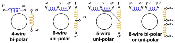
Figure 1. Stepper motor wiring diagrams.
Use an ohm meter to determine type.
Arduino Unipolar Stepper Motor Control
by Lewis Loflin
For the hobbyist, one way to distinguish common wire from a coil-end wire is by measuring the resistance. Resistance between common wire and coil-end wire is always half of what it is between coil-end and coil-end wires. This is due to the fact that there is actually twice the length of coil between the ends and only half from center (common wire) to the end.
Here we will examine the basic operation of a unipolar stepper motor. I'll cover a bipolar stepper motor on a different page. A unipolar stepper motor has two windings per phase, one for each direction of magnetic field.
Since in this arrangement a magnetic pole can be reversed without switching the direction of current, the commutation circuit can be made very simple (eg. a single transistor) for each winding.
Typically, given a phase, one end of each winding is made common: giving three leads per phase and six leads for a typical two phase motor. Often, these two phase commons are internally joined, so the motor has only five leads. Others can have six leads.
A micro controller or stepper motor controller can be used to activate the drive transistors in the right order, and this ease of operation makes unipolar motors popular with hobbyists. They are probably the cheapest way to get precise angular movements.
Bipolar motor: Bipolar motors have a single winding per phase. The current in a winding needs to be reversed in order to reverse a magnetic pole, so the driving circuit must be more complicated, typically with an H-bridge arrangement. There are two leads per phase, none are common.
Stepper motors consist of a permanent magnet rotating shaft, called the rotor, and electromagnets on the stationary portion that surrounds the motor, called the stator. Controlling the sequence will cause the rotor to move. The electromagnets are energized by an external control circuit, such as a micro controller.
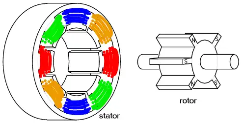
Figure 2. Basic stepper motor construction.
Figure 3. Two phases on for more torque.
When half stepping, the drive alternates between two phases on and a single phase on. This increases the angular resolution (less degrees per step), but the motor also has less torque at the half step position (where only a single phase is on). This may be mitigated by increasing the current in the active winding to compensate. The advantage of half stepping is that the drive electronics need not change to support it. In the examples below I only use two-phase single step for high torque.
For more technical detail see Stepper Motor Basis from Microchip. (PDF file)
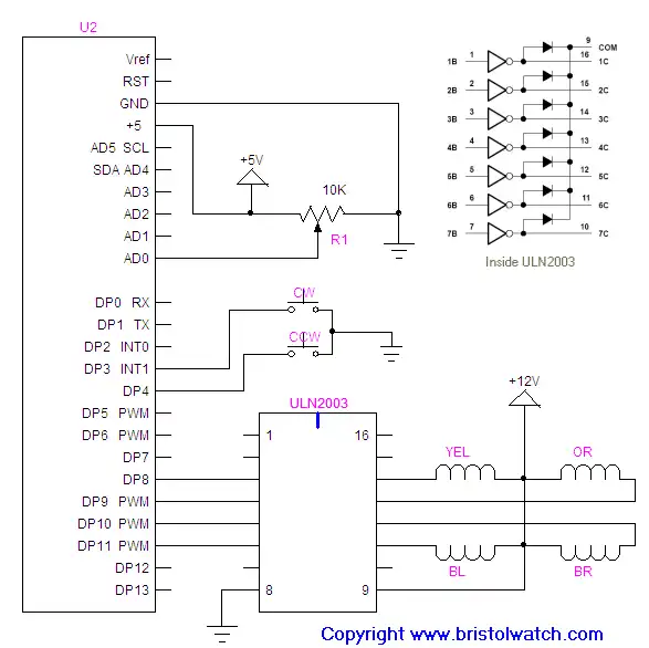
Schematic for this program.
- Basic Transistor Driver Circuits for Micro-Controllers
- Opto-Isolated Transistor Drivers for Micro-Controllers
- Stepper Motor Arduino Programs
- stepper_arduino1.txt
- stepper_arduino2.txt
Date: 7-11-2021
- YouTube videos:
- Constant Current Source Multimeter Trouble Shooting
- Ohm's Law Review for Constant Current Source
- Arduino Unipolar Stepper Motor Driver Board with Arduino Code
- Arduino Controlled Constant Current Source
- Quick navigation of this website:
- Basic Electronics Learning and Projects
- Basic Solid State Component Projects
- Arduino Microcontroller Projects
- Raspberry Pi Electronics, Programming
Stepper Motors
- Easy Driver Micro-Stepper Controller to Arduino
- Unipolar Stepper Motor with a Arduino
- Considerations for Using Stepper Motors
- Connecting the Arduino to a L298N H-Bridge
- L298N Motor Controller Theory and Projects
- TA8050 H-Bridge Motor Controller
- Battery Charger related:
- Solar Panel Charge Controller Using Arduino
- Solar Panel Battery Charge Controller Using Arduino
- Solar Panel Battery Charge Controller Switching Circuit
- Arduino AC Power Control Tutorial
- Rotary Encoder Using Arduino Hardware Interrupts
- Arduino Controlling 74C164 Shift Register
- Arduino Interface MC3479 Stepper Motor Controller
Serial LCD Display and assorted Sensors
- Arduino LCD Display using 74164 Shift Register
- Arduino LCD Display with DS18B20
- Arduino LCD Display with DHT11 Sensor
- Arduino with MM5451 LED Display Driver
- Arduino MAX7219 Operates 8X8 LED Matrix
- Arduino RTC Clock MAX7219 LED Display
- BCD Conversion with MAX7219
- Hatching Chicken Eggs with Arduino
- Arduino TMP37 Temperature Sensor
- Arduino TMP37 Temperature Sensor Tutorial
- Testing the Keyes IR Sensor Module with Arduino
- Arduino to MCP23016, LCD Display
- Time-Date with Arduino, LCD Display, DS1307 RTC
- Controlling Driveway Lights with the Arduino
- TSL230R Light to Frequency Converter
- Arduino with MCP23016 I/O Expander
- Arduino DS1307 Real Time Clock
- Arduino with 24LC08 Serial EEPROM
- MC3479 Stepper Motor Controller with Arduino
Web site Copyright Lewis Loflin, All rights reserved.
If using this material on another site, please provide a link back to my site.