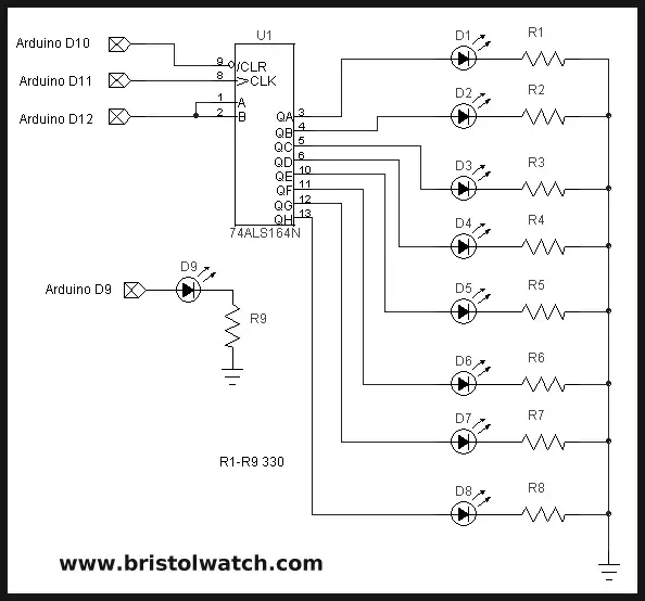
Fig. 1 electrical connections to Arduino.
Arduino Controlling 74C164 Shift Register
This sample circuit and program demonstrate the use of a shift register with an Arduino Microcontroller. Instead of using some pre-made library, the idea here is use ones own code and learn some electronics.
For more on differing LED configurations see Using the 74HC165 Shift Register with the PICAXE Micro-Controller
This demonstration will use 8 light emitting diodes (LEDs) to count in binary from 0 to 255. This will require eight bits or one byte. How this count is displayed depends on how the LEDs are connected and how the bits are shifted into the shift register.
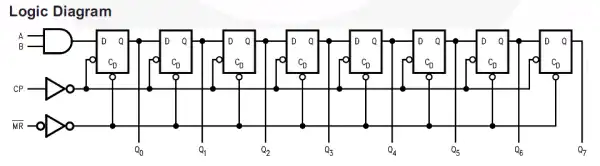
Fig. 2 internal block diagram of the 74HC164.
Fig. 2 above shows a typical internal block diagram of a eight-bit shift register. In the case of the 74HC164 we have eight clocked "D" type flip-flops with common clock line (CP) and common reset line (MR NOT) that will set outputs Q0 - Q7 to all LOW or binary 0. Note in the electrical sense a HIGH or binary 1 will output (source) +5-volts while a binary 0 will switch (sink) the pin to ground.
The 74HC164 8-Bit Serial-In - Parallel-Out Serial Shift Register has three inputs:
- Input A-B (pins 1, 2) is for data bit to be shifted in. They can be tied together or the one not used ties to +Vcc.
- CP or clock pin 8 data is shifted into the 8-bit register during the positive going transition of clock pulse. That is, whatever the state of input A-B will be shift one-bit right during each clock cycle and will continue to be shifted right during each consecutive pulse.
- Clear (pin 9) is independent of the clock and when taken LOW (0 volts), Q0 - Q7 will all go LOW (ground) on the corresponding output pin. This pin must be initialized/held HIGH for the register to operate.
Arduino code for this project: arduino3a.txt
- YouTube videos for this project:
- 74C164 shift register with Microchip PIC Part 1
- 74C164 shift register with Arduino Part 2
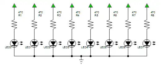
Common cathode configuration.
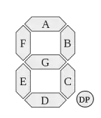
Connected to 7-segment Display
This program assumes a seven segment display with a bit pattern:
Q7 segment a
Q6 segment b
Q5 segment c
Q4 segment d
Q3 segment e
Q2 segment f
Q1 segment g
Q0 segment dp
Arduino code for this project: arduino3a.txt
- Quick navigation of this website:
- Basic Electronics Learning and Projects
- Basic Solid State Component Projects
- Arduino Microcontroller Projects
- Raspberry Pi Electronics, Programming
Stepper Motors
- Easy Driver Micro-Stepper Controller to Arduino
- Unipolar Stepper Motor with a Arduino
- Considerations for Using Stepper Motors
- Connecting the Arduino to a L298N H-Bridge
- L298N Motor Controller Theory and Projects
- TA8050 H-Bridge Motor Controller
- Battery Charger related:
- Solar Panel Charge Controller Using Arduino
- Solar Panel Battery Charge Controller Using Arduino
- Solar Panel Battery Charge Controller Switching Circuit
- Arduino AC Power Control Tutorial
- Rotary Encoder Using Arduino Hardware Interrupts
- Arduino Controlling 74C164 Shift Register
- Arduino Interface MC3479 Stepper Motor Controller
Serial LCD Display and assorted Sensors
- Arduino LCD Display using 74164 Shift Register
- Arduino LCD Display with DS18B20
- Arduino LCD Display with DHT11 Sensor
- Arduino with MM5451 LED Display Driver
- Arduino MAX7219 Operates 8X8 LED Matrix
- Arduino RTC Clock MAX7219 LED Display
- BCD Conversion with MAX7219
- Hatching Chicken Eggs with Arduino
- Arduino TMP37 Temperature Sensor
- Arduino TMP37 Temperature Sensor Tutorial
- Testing the Keyes IR Sensor Module with Arduino
- Arduino to MCP23016, LCD Display
- Time-Date with Arduino, LCD Display, DS1307 RTC
- Controlling Driveway Lights with the Arduino
- TSL230R Light to Frequency Converter
- Arduino with MCP23016 I/O Expander
- Arduino DS1307 Real Time Clock
- Arduino with 24LC08 Serial EEPROM
- MC3479 Stepper Motor Controller with Arduino
Web site Copyright Lewis Loflin, All rights reserved.
If using this material on another site, please provide a link back to my site.