Arduino Interface MC3479 Stepper Motor Controller
by Lewis Loflin
Note: the MC3479 is an obsolete part and hard to get. Use Easy Driver to do the same thing. See How to Connect Easy Driver Micro-Stepper Controller to Arduino
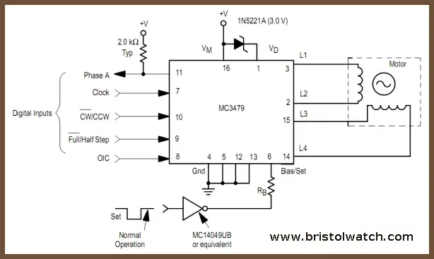
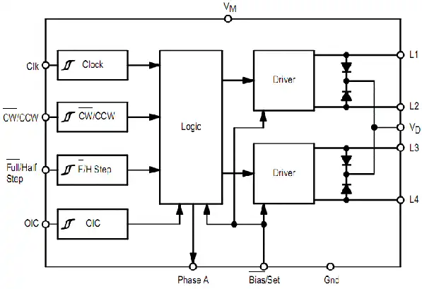
The MC3479 is designed to drive a two-phase (bipolar) stepper motor. The circuit (see above) consists of four input sections, a logic decoding/sequencing section, two driver-stages for the motor coils. Here we will look at using the advanced features of the Mc3479 while over coming its limitations. The basic specs are as follows:
- Single Supply Operation: 7.2 to 16.5 V
- 350 mA/Coil Drive Capability
- Clamp Diodes Provided for Back-EMF Suppression
- Selectable CW/CCW and Full/Half Step Operation
- Selectable High/Low Output Impedance (Half Step Mode)
- TTL/CMOS Compatible Inputs
On the plus side the inputs can be standard TTL (5-volt logic) or CMOS, while the power supply must be at least 7-volts or the inputs won't operate correctly. Thus it's the power supply requirements that won't allow the use of 5-volt stepper motors. The 350 mA drive coil current is on the low side. That current can be controlled by the resistor Rb from a calculation in the spec sheet. The logic control circuits in the IC are powerful and work very well. The part is getting hard to find.
My goal here is to overcome these problems while using the power logic features of the Mc3479. By the use of opto-couplers we can get beyond the voltage and current limitations of this component while utilizing its advanced features. This includes operating both unipolar and bipolar stepper motors, which use the same switching codes anyway.
MC3479 universal stepper motor control diagram.
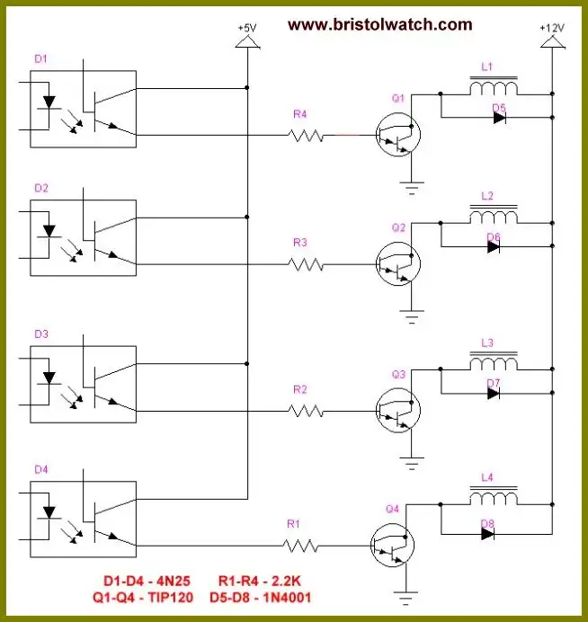
Opto coupler connections Mc3479 to unipolar stepper motor. If being used with a L298 module as shown in video connect each opto-coupler emitter to ground through a 1000 ohm resistor.
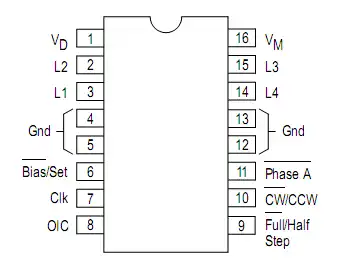
MC3479 package and electrical connections.
In the program below SW0 SW1 SW7 are simply connected through Arduino to the Mc3479 pins. A clock pulse is produced to whose speed is based on the values of a potentiometer connected to Analog pin 0.
/* Mc3479 Demo */

#define SW0 3 // input sw0
#define SW1 4 // Sw1 input
#define SW7 8 // Sw7 input

#define MC3479_clk 10
// connect to MC3479 pin 7
#define MC3479_HF_step 12
// connect to MC3479 pin 9
#define MC3479_dir 11
// connect to MC3479 pin 10
#define MC3479_enable 9
int temp;


void setup() {
pinMode(SW0, INPUT);
pinMode(SW1, INPUT);
pinMode(SW7, INPUT);

pinMode(MC3479_clk, OUTPUT);
pinMode(MC3479_HF_step, OUTPUT);
pinMode(MC3479_dir, OUTPUT);
pinMode(MC3479_enable, OUTPUT);

digitalWrite(MC3479_clk, LOW);
digitalWrite(MC3479_HF_step, LOW);
digitalWrite(MC3479_dir, LOW);
digitalWrite(MC3479_enable, LOW);

}

void loop() {

temp = analogRead(0) / 2;
toggle(MC3479_clk);
delay(3);
toggle(MC3479_clk);
delay(temp);
// read switch transfer to output
digitalWrite(MC3479_HF_step, digitalRead(SW0));
digitalWrite(MC3479_dir, digitalRead(SW1));
digitalWrite(MC3479_enable, digitalRead(SW7));
// steps(5000);
}

void steps(int j) {

for (int i = 0; i < j; i++) {
digitalWrite(MC3479_clk, 1);
delay(3);
digitalWrite(MC3479_clk, 0);
delay(analogRead(0) / 2);
} // end for
} // end steps

void toggle(int pinNum) {

int pinState = digitalRead(pinNum);
pinState = !pinState;
digitalWrite(pinNum, pinState);
}
- Quick navigation of this website:
- Basic Electronics Learning and Projects
- Basic Solid State Component Projects
- Arduino Microcontroller Projects
- Raspberry Pi Electronics, Programming
Stepper Motors
- Easy Driver Micro-Stepper Controller to Arduino
- Unipolar Stepper Motor with a Arduino
- Considerations for Using Stepper Motors
- Connecting the Arduino to a L298N H-Bridge
- L298N Motor Controller Theory and Projects
- TA8050 H-Bridge Motor Controller
- Battery Charger related:
- Solar Panel Charge Controller Using Arduino
- Solar Panel Battery Charge Controller Using Arduino
- Solar Panel Battery Charge Controller Switching Circuit
- Arduino AC Power Control Tutorial
- Rotary Encoder Using Arduino Hardware Interrupts
- Arduino Controlling 74C164 Shift Register
- Arduino Interface MC3479 Stepper Motor Controller
Serial LCD Display and assorted Sensors
- Arduino LCD Display using 74164 Shift Register
- Arduino LCD Display with DS18B20
- Arduino LCD Display with DHT11 Sensor
- Arduino with MM5451 LED Display Driver
- Arduino MAX7219 Operates 8X8 LED Matrix
- Arduino RTC Clock MAX7219 LED Display
- BCD Conversion with MAX7219
- Hatching Chicken Eggs with Arduino
- Arduino TMP37 Temperature Sensor
- Arduino TMP37 Temperature Sensor Tutorial
- Testing the Keyes IR Sensor Module with Arduino
- Arduino to MCP23016, LCD Display
- Time-Date with Arduino, LCD Display, DS1307 RTC
- Controlling Driveway Lights with the Arduino
- TSL230R Light to Frequency Converter
- Arduino with MCP23016 I/O Expander
- Arduino DS1307 Real Time Clock
- Arduino with 24LC08 Serial EEPROM
- MC3479 Stepper Motor Controller with Arduino
Web site Copyright Lewis Loflin, All rights reserved.
If using this material on another site, please provide a link back to my site.