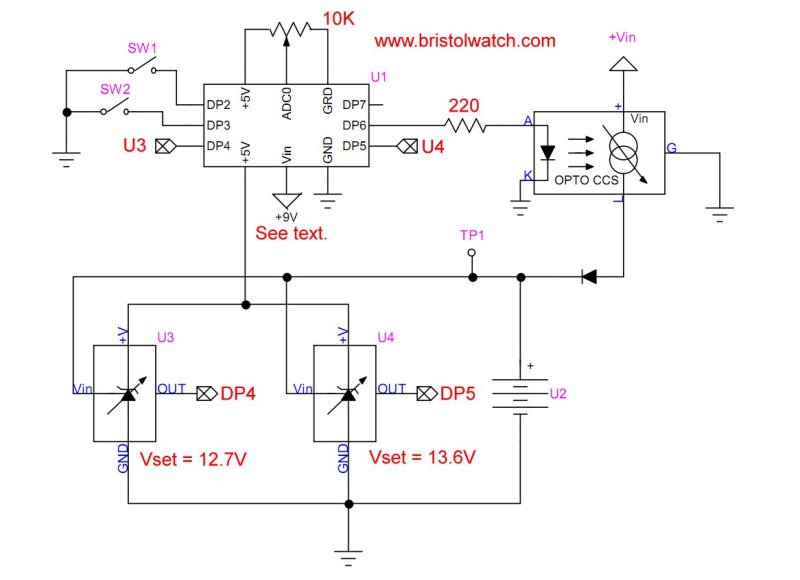
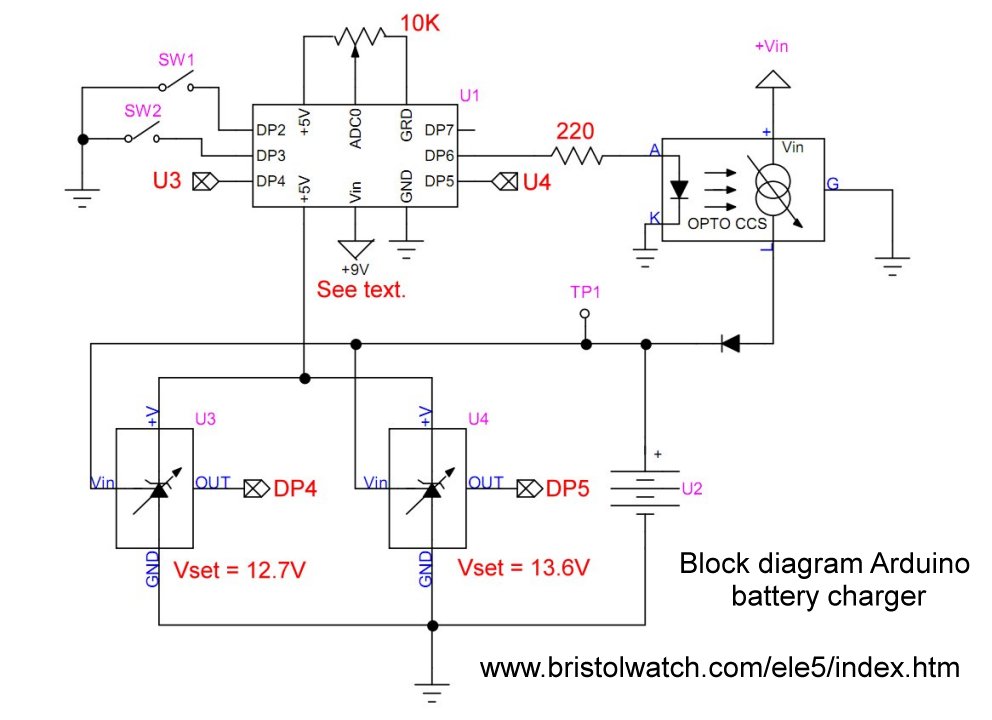
Fig. 1 Arduino battery charger with opto-isolated
CCS and 2 TL431 voltage comparators.
Click for larger image.
Solar Panel Battery Charge Controller Switching Circuit
by Lewis Loflin
Follow @Lewis90068157
Note: Indicator LEDs DP9, DP10, and DP11 not shown in schematic.
Related circuits and theory see the following:
- TL431 Battery Charger Voltage Detector Circuits Schematics
- Arduino Constant Current H-Bridge Motor Control
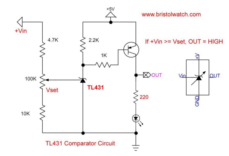
Fig. 2 A TL431 shunt regulator circuit configured
as a voltage comparator.
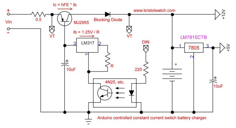
Fig. 3 Optocoupler controlled constant current source
with LM317 and +5V regulator.
Click for larger image.

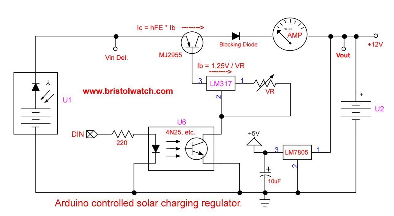
Fig. 4 Optocoupler controlled constant current source with
LM317 and +5V regulator for solar panel Charging.
Click for larger image.
- Battery Charger related:
- Arduino Solar Panel Battery Charge Controller Switching Circuit
- TL431A Lithium-Ion Cell Charging Circuits
- Charging Multi-Cell Lithium-Ion Battery Packs
- TL431 Battery Charger Voltage Detector Circuits Schematics
- TL431 Battery Charger Voltage Detector Circuits Schematics
Video: Arduino Battery Charger uses CCS and TL431 Comparators
Arduino Code for Above Circuits
/*
	Arduino TL431 CCS Battery Charger
	Use pwm to control output current
	for constant current source. Use
	TL431 voltage detector.
	Connect both TL431 circuits to battery.
	PWM duty cycle is based on the TL431 comparators.
	by Lewis Loflin www.bristolwatch.com
*/

#define POT 0
#define PB1 2
#define PB2 3
#define TL431A 4
#define TL431B 5
#define pwmOut 6

// values measured on resistive load
// CCS set for 1.14A max.
#define ccsHigh 255
#define ccsMed 144
#define ccsLow 45
#define ccsOff 0

int temp = 0;

void setup() {
  // PB1, PB2 LOW if pushed, otherwise HIGH
  // yes I know about INPUT_PULLUP
  pinMode(PB1, INPUT);
  digitalWrite(PB1, HIGH);  // pullup
  pinMode(PB2, INPUT);
  digitalWrite(PB2, HIGH);  // pullup

  // High from TL431 Vin > Rset
  pinMode(TL431A, INPUT);  // Vin battery LOW
  pinMode(TL431B, INPUT);  // Vin battery HIGH

  pinMode(pwmOut, OUTPUT);  // To CCS optocoupler
  Serial.begin(9600);
  Serial.println("Serial OK");
}

void loop() {

void loop() {

  if (digitalRead(PB1) == 1 && digitalRead(PB2) == 1) {
    temp = analogRead(POT) / 4;
    delay(1000); // wait for release
  }  // variable 0-1 Amps

  if (digitalRead(PB1) == 0 && digitalRead(PB2) == 1) {
    temp = ccsHigh;
    delay(1000); // wait for release
  }  // 1 Amp

  if (digitalRead(PB1) == 1 && digitalRead(PB2) == 0) {
    temp = ccsMed;
    delay(1000); // wait for release
  }  // 0.5 Amps

  if (digitalRead(PB1) == 0 && digitalRead(PB2) == 0) {
    temp = ccsLow;
    delay(1000); // wait for release
  }  // 0.25 Amps

  analogWrite(pwmOut, temp);
  Serial.println("PWM value = ");
  Serial.println(temp);

  delay(5000);  // wait 5 Sec.

} // end loop
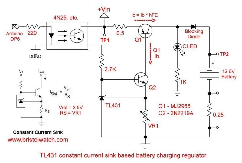
Fig. 5 TL431 based sink-current regulator driving high current constant current
source with optocoupler ON-OFF control.
Click for larger image.
- Comparator Circuits:
- Comparator Theory Circuits Tutorial
- Comparator Hysteresis and Schmitt Triggers
- Voltage Comparator Information And Circuits
- Looking at Window Comparator Circuits
- Analog Battery Charger Uses Comparators
- Battery Charger related:
- Solar Panel Charge Controller Using Arduino Microcontroller
- Solar Panel Charge Controller Using PICAXE Microcontroller
- Videos:
- My YouTube Videos on Electronics
- Introduction to the Arduino Microcontroller
- Part 1: Programming Arduino Output
- Part 2: Programming Arduino Input
- Part 3: Arduino Analog to Digital Conversion
- Part 4: Using Arduino Pulse-Width-Modulation
- Zero-Crossing Detectors Circuits and Applications
- Zero-Crossing Circuits for AC Power Control
- In Depth Look at AC Power Control with Arduino
- Micro-controller AC Power Control Using Interrupts
- YouTube Video for Arduino AC Power Control
- Photo Detector Devices:
- LM334 CCS Circuits with Thermistors, Photocells
- Photodiode Circuits Operation and Uses
- Photodiode Op-Amp Circuits Tutorial
- Photo Voltaic Tutorial MOSFET Output Solid State Relays
- YouTube:
- Photodiodes and How they Work
- Photodiode Op-Amp Circuits
- Using Photovoltaic MOSFET Drivers
Web site Copyright Lewis Loflin, All rights reserved.
If using this material on another site, please provide a link back to my site.