
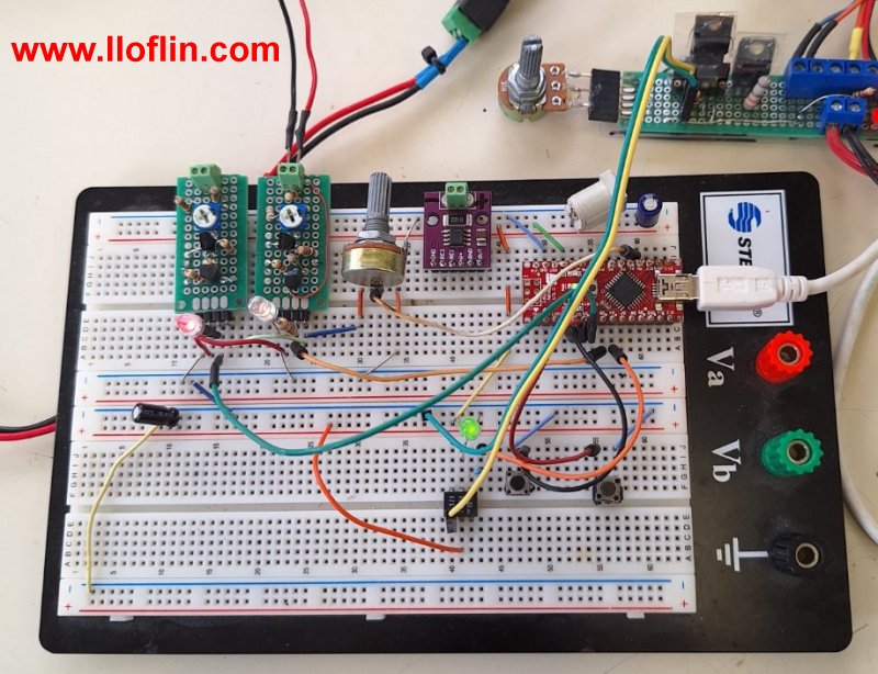
Fig. 1 Arduino battery charger with two TL431 voltage detectors.
TL431 Battery Charger Voltage Detector Circuits Schematics
by Lewis Loflin
Above: Click for larger image.
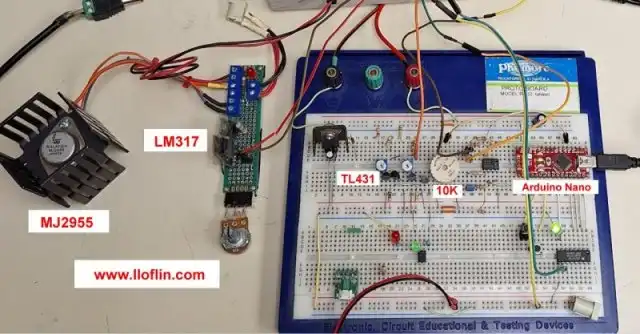
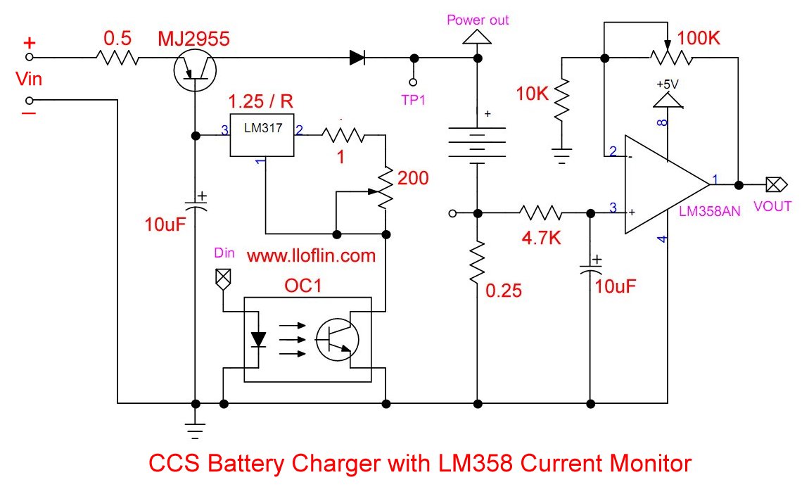
Fig. 2 Arduino with TL431 voltage detectors control
battery charge current with LM317-MJ2955.
Click for larger image.
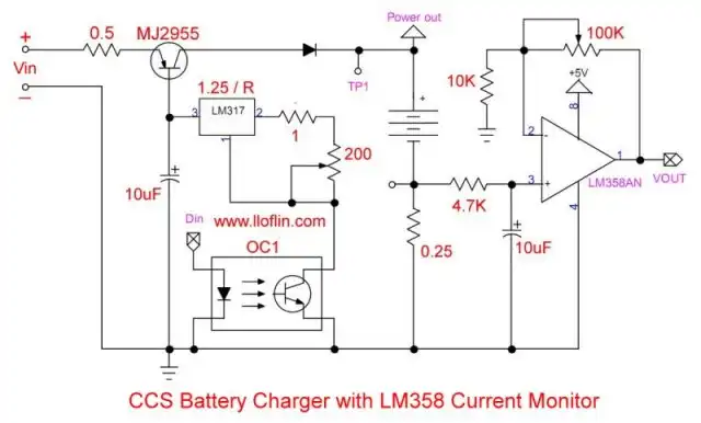
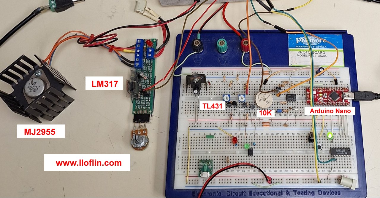
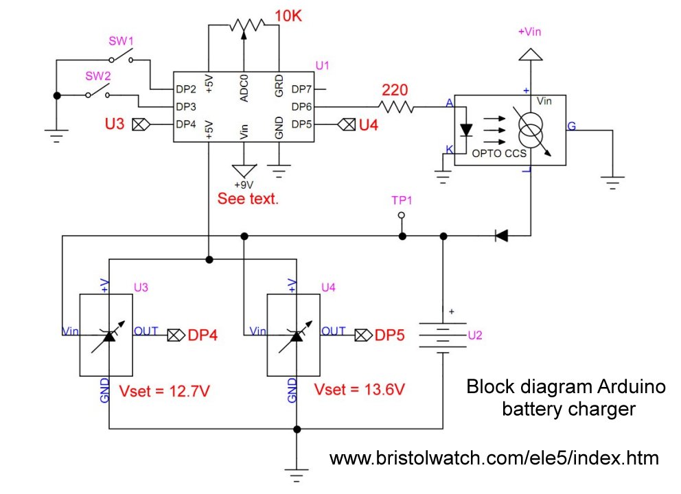
Fig. 3
Click for larger image.
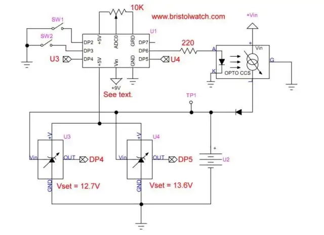
Fig. 4 Arduino battery charger with opto-isolated
CCS and 2 TL431 voltage comparators.
Click for larger image.
Note: Indicator LEDs DP9, DP10, and DP11 not shown.
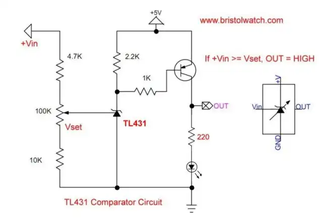
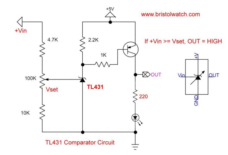
Fig. 5 A TL431 shunt regulator circuit configured
as a voltage comparator.
Above: Click for larger image.
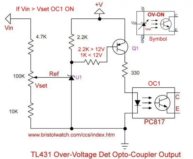
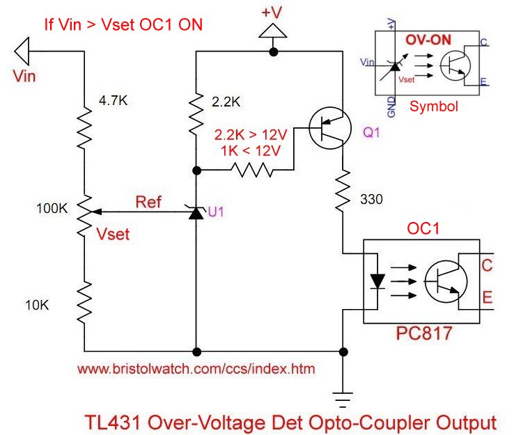
Fig. 6 TL431 over voltage detector with optocoupler output.
Above: Click for larger image.
- Arduino Measures Current from Constant Current Source
- Arduino Controlled Power Constant Current Source
- TL431 Battery Charger Voltage Detector Circuits Schematics
- Arduino Constant Current H-Bridge Motor Control
- TL431 Battery Charger Voltage Detector Circuits Schematics
- TL431 Sink Mode Constant Current Circuits
Arduino Code for Above Circuits
/*
  Use pwm to control output current
  for constant current source for battery charger
*/

#define TL431A 4 // HIGH out V = set
#define TL431B 5 // HIGH out V = set
#define pwmOut 6

// 1K resistor to GRD.
#define redLed 11
#define yellowLed 10
#define greenLed 9

#define ccsHigh 255 // 100%
#define ccsMed 144 // 50%
#define ccsLow 45 // 25%
#define ccsOff 0 // 0% or OFF

int temp = 0;

void setup() {

  // High from TL431 Vin > Rset
  pinMode(TL431A, INPUT);  // Rset = 12.6V
  pinMode(TL431B, INPUT);  // Rset = 13.6V

  pinMode(redLed, OUTPUT);
  pinMode(yellowLed, OUTPUT);
  pinMode(greenLed, OUTPUT);

  pinMode(pwmOut, OUTPUT); // CCS optocoupler
  Serial.begin(9600);
  Serial.println("Serial OK");
}

void loop() {
  // battery voltage less than 12.6V
  if (digitalRead(TL431A) == 0 && digitalRead(TL431B) == 0) {
    digitalWrite(redLed, HIGH); // high charge rate
    digitalWrite(yellowLed, LOW);
    digitalWrite(greenLed, LOW);
    delay(500);
    temp = ccsHigh;
  }   // 1 Amp

  // battery voltage 12.6V to 13.6V
  if (digitalRead(TL431A) == 1 && digitalRead(TL431B) == 0) {
    digitalWrite(redLed, LOW);
    digitalWrite(yellowLed, HIGH); // medium charge rate
    digitalWrite(greenLed, LOW);
    delay(500);
    temp = ccsMed; // slow charge rate can use ccsLow
  }   // 0.5 Amps

  // battery voltage V > 13.6V
  if (digitalRead(TL431A) == 1 && digitalRead(TL431B) == 1) {
    digitalWrite(redLed, LOW);
    digitalWrite(yellowLed, LOW);
    digitalWrite(greenLed, HIGH); // charged
    delay(500);
    temp = ccsOff; // charged turn off
  }   // 0 Amps

  analogWrite(pwmOut, temp);
  Serial.print("PWM value = ");
  Serial.println(temp);
  delay(5000);  // delay 5 Sec.
}
Related see TL431 Battery Charger Voltage Detector Circuits Schematics
- Using TL431A Li-Ion Battery Charger Tutorials
- TL431A Lithium-Ion Cell Charging Circuits
- Charging Multi-Cell Lithium-Ion Battery Packs
- TL431 Over-Voltage, Under-Voltage Detector Circuits
- TL431A Constant Current Source Working Circuits Demo
- Power TL431 Constant Current Source Circuits
Related YouTube videos.
- TL431 12V Battery Charger Complete
- TL431A Lithium-Ion Cell Charging Circuits
- TL431 Battery Charger Circuit Calculations Revised
- TL431 10-Volt Charger Short Version
- Charging, Charge-Balancing 18V Li-Ion Battery with TL431
- 18.5V Li-Ion Battery Charger with TL431 short version
- TL431 Under-Voltage, Over-Voltage Detection
- TL431 Constant Current Source Circuits
- LM317 Adjustable Current Boost Power Supply
- Constant Current Circuits LM334, LM317
- Build LM317 0-34 Volt Power Supply
- LM334 Constant Current Source with Resistive Sensors
- LM317 High Power Constant Current Source Circuit
- LM317 Constant Current Source Circuits
- Test SCRs and Triacs
- Basic MOSFET Transistor Test Circuits
- High Voltage MOSFET Switching Circuits
- 3 Amp LM741 Op-Amp Constant Current Source
- Current Limiter Testing of Zener Diodes
- Current Limiter for Opto-Coupler Inputs
- LM317 CCS for Light Emitting Diodes
Other Circuits
- Hall Effect Magnetic Switches and Sensors
- Comparator Theory Circuits Tutorial
- ULN2003A Darlington Transistor Array with Circuit Examples
- Transistor-Zener Diode Regulator Circuits
- AC Power Supply Rectification
- Coils for Highly Selective Crystal Radio
- Neon (NE-2) Circuits You Can Build
- Photodiode Circuits Operation and Uses
- Photodiode Op-Amp Circuits Tutorial

![]()
Web site Copyright Lewis Loflin, All rights reserved.
If using this material on another site, please provide a link back to my site.