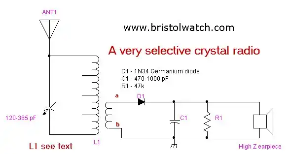
Tuning Coil Construction High Selectivity Crystal Radios
When I was a kid I built my first crystal radio. It had no tuning capacitor, it brushed a metal contact across a copper coil where the varnish had been sanded off with sand paper.
Here 50 years later I wanted a better version. The information below had been derived from several sources. Much of this project was based on a "Mystery Crystal Radio" from the 1930s and the ARRL Handbook of 1977.
This is all highly experimental and I can promise the outcome will vary, but it will work. One final note on this coil is the two output connections (a, b) can be reversed for better volume.
Don't connect the ground to the tuner side of the coil. The output from the diode was connected to my LM386 utility amplifier and produced good results on a 20 foot wire. For more on the amplifier see LM386 Power Amplifier
The coil is hand made and one can experiment with the number of windings. This is very selective and pulled in several local stations and some of the short wave bands as well. L1 is based on a 1930s design and the purpose here is to teach some basic radio design.
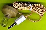
Typical High-Z crystal earpiece.
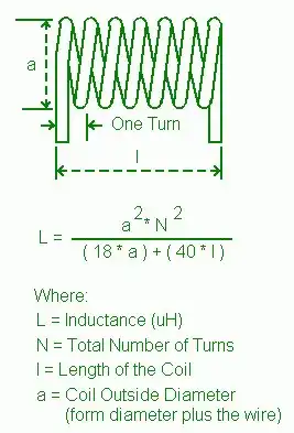
The Length-to-Diameter Ratio of a coil can affect the Q of a single-layer close-wound coil. A high Q insures improved circuit efficiency, a narrower bandwidth and less wide-band noise in oscillator circuits. (Thus better selectivity or the ability to separate stations.) In designing a high Q coil the following parameters should be considered:
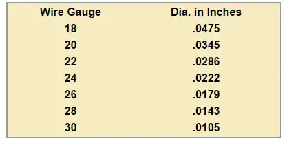
- The wire size should be as large as practicable.
- The turn spacing should be as close as practicable. (If small coils space between turns will give a higher "Q".)
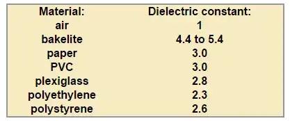
- The coil form should have a low dielectric constant. Air is best, there should be no metal near the coil.
- The Length-to-Diameter Ratio should not exceed 4:1. Ratios of between 1:1 and 2:1 are preferred for most circuits.
Note the AM Broadcast (U.S.) 535-1705 kHz. We need 229uH coil to work with a 500 pf variable cap based on various formulas I used on the 1930s coil. My coil length to diameter ratio came out to 2.1:1.
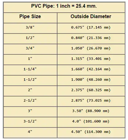
The author of the 1932 article used a 3 inch O.D. coil form (use PVC pipe) which calculates out to 229uH. Punch two holes in the form and secure the 24-gauge, then wind 12 turns and stop. Punch two more holes to secure the 30-gauge wire and wind both together for 25 turns. Punch two more holes to secure the 30-gauge wire, wind another 13 turns of 24-gauge wire. Punch two more holes to secure the 24-gauge wire, leave six inches on each.
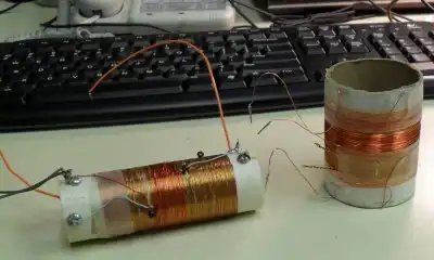
Two coils I made for this project.
With mine I used 1 inch PVC (1.315 O.D.) where I wound 100 turns close wound of 24-gauge then wound 25 turns of 24-gauge centered over the first coil. This came out to 154uH depending on which coil calculator I used for the first coil. The frequency was way too high (inductance too low) so I inserted a ferrite bar into the coil and brought it into the range of 220-230uH. Otherwise I couldn't tune in stations below 600 kHz. Note there will be variations due to construction technique, antenna length, etc.
The second coil used a 2 inch diameter cardboard tube and 75 turns on the main coil and again 25 turns for the secondary.
The tuning capacitor was an antique unit from a five tube table radio. Use both sections together to get from about 20 pF to 510 pF.
Before I began to wind the first coil I threaded the wire through four glass beads and placed them at 20 turns, 40 turns, and 70 turns. The exposed windings could be used as taps. Also note it would help to cover the coil form with double-sided scotch tape before hand to help hold the windings in place.
12AV6 Vacuum Tube Radio with LM386 Power Amplifier
Grid-Leak Detector Low Voltage Vacuum Tube Radio
- Build 12AV6 Vacuum Tube AM Radio
- Coils for Highly Selective Crystal Radio
- Add Push-Pull Output Stage LM386 Audio Amplifier
- Arduino Stepper Motor Drive Coil Winder
- Quick navigation of this website:
- Basic Electronics Learning and Projects
- Basic Solid State Component Projects
- Arduino Microcontroller Projects
- Raspberry Pi Electronics, Programming
- Added Nov. 16, 2014
- ULN2003A Darlington Transistor Array with Circuit Examples
- Tutorial Using TIP120 and TIP125 Power Darlington Transistors
- Driving 2N3055-MJ2955 Power Transistors with Darlington Transistors
- Understanding Bipolar Transistor Switches
- N-Channel Power MOSFET Switching Tutorial
- P-Channel Power MOSFET Switch Tutorial
- More Power MOSFET H-Bridge Circuit Examples
- Build a High Power Transistor H-Bridge Motor Control
Web site Copyright Lewis Loflin, All rights reserved.
If using this material on another site, please provide a link back to my site.