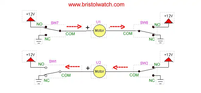
Figure 1 very basic H-bridge.
Build a High Power Transistor H-Bridge Motor Control
by Lewis Loflin
So far in this series we've looked at several types of transistor and MOSFET switching circuits. Now we will tie all of that together and build a bipolar transistor H-bridge motor control. Looking once again at fig. 1 we see that a H-bridge is simply four switches, two tied to ground, two tied to Vcc, and a motor connected between the commons.
In the case above with mechanical switches only when one of the Vcc switches on one side and the ground connected switch on the other side is at ground do we complete the current path and the motor will run. Now we will replace mechanical switches with bipolar transistors.
Here we are using the TIP120 and TIP125 Darlington power transistors. See Tutorial Using TIP120 and TIP125 Power Darlington Transistors
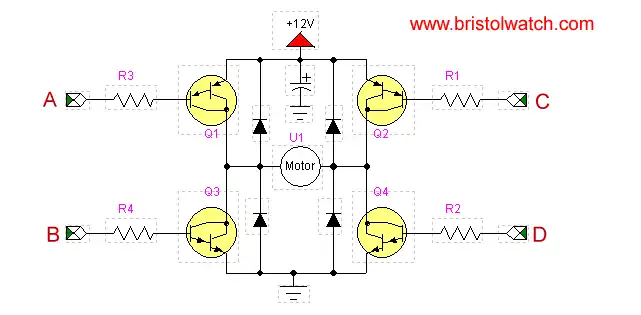
Figure 2
In fig. 2 we have our basic transistor H-bridge. This consists of two PNP and two NPN Darlington transistors. In addition we have four diodes to suppress noise and voltage spikes. From here on I'll leave out the diodes, but they will be needed if they aren't internally built into the transistors.
If one hasn't read my other pages know now that LOW or 0-volts on A or C will switch on Q1 or Q2. A HIGH or positive voltage input on C or D will switch on Q3 or Q4.
Caution: avoid switching on Q1 and Q3 or Q2 and Q4 AT THE SAME TIME! This will create a condition known as "shoot through" shorting out the power supply and damaging the transistors.
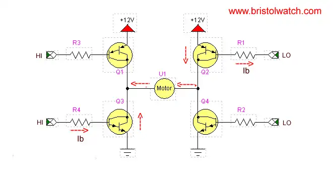
Figure 3
In fig. 3 we have created a current path for the motor by switching on Q3 with a HIGH input and switching on Q2 with a LOW. Rotation direction on DC permanent magnet motor is dependant on the direction of current flow.
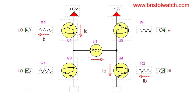
Figure 4
In fig. 4 we have created a reverse current path relative to the motor with a LOW on Q1 and a HIGH on Q4.
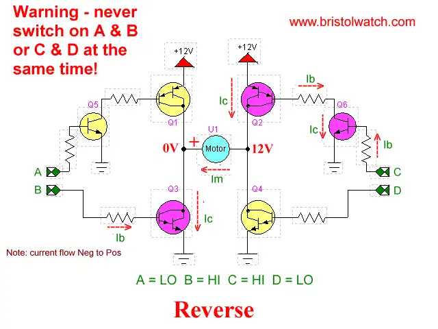
Figure 5
In fig. 5 we have added two additional transistors Q5 and Q6. This has overcome the pitfall of being unable to connect the circuit to a micro-controller because of the 12-volts present on R1 and R3. Q5-Q6 block that voltage and with proper selection of base resistors allow 5-volt operation. A HIGH on B and a HIGH on C will turn on the motor. Using a 2N2222 for Q5-Q6 and a hfe of over 1000 on Q1-Q4 we can use 2.2K resistors.
In fact with proper circuit modifications one could use low-power MOSFETs or Darlington transistors - or even CMOS gates if Vcc is under 15-volts.
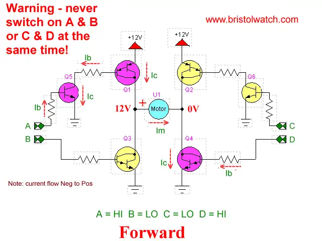
Figure 6
Finally we reversed the direction of the motor with a HIGH on A and D with a LOW B and C.
I hope the series was helpful. Any corrections, suggestions etc. e-mail me at lewis@bvu.net.
![]()
- Quick navigation of this website:
- You Tube Channel
- Basic Electronics Learning and Projects
- Basic Solid State Component Projects
- Arduino Microcontroller Projects
- Raspberry Pi Electronics, Programming
- ULN2003A Darlington Transistor Array with Circuit Examples
- Tutorial Using TIP120 and TIP125 Power Darlington Transistors
- Driving 2N3055-MJ2955 Darlington Transistors
- Understanding Bipolar Transistor Switches
- N-Channel Power MOSFET Switching Tutorial
- P-Channel Power MOSFET Switch Tutorial
- H-Bridge Motor Control with Power MOSFETs
- Arduino Controlled IR2110 Based H-Bridge HV Motor Control
- IGBT Based High Voltage H-Bridge DC Motor Control
- More Power MOSFET H-Bridge Circuit Examples
- Build a High Power Transistor H-Bridge Motor Control
- Related:
- N-Channel Power MOSFET Switching Tutorial
- P-Channel Power MOSFET Switch Tutorial
- Test Power MOSFET Transistors, Observations
- Issues on Connecting MOSFETs in Parallel
- Basic MOSFET Transistor Test Circuits
- High Voltage MOSFET Switching Circuits
- Why Your MOSFET Transistors Get Hot YouTube
- Issues on Connecting MOSFETs in Parallel YouTube
- Simple Circuits for Testing MOSFET Transistors YouTube
See the following spec sheets:
- Basic Triacs and SCRs
- Constant Current Circuits with the LM334
- LM334 CCS Circuits with Thermistors, Photocells
- LM317 Constant Current Source Circuits
- TA8050P H-Bridge Motor Control
- All NPN Transistor H-Bridge Motor Control
- Basic Triacs and SCRs
- Comparator Theory Circuits Tutorial
Web site Copyright Lewis Loflin, All rights reserved.
If using this material on another site, please provide a link back to my site.