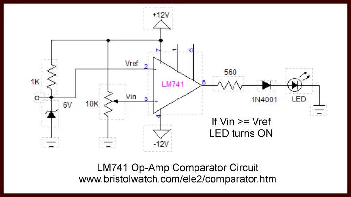
Fig. 1 LM741 based comparator
uses bipolar power supply.
Comparator Circuits Examples Tutorial
Comparators are every for allowing digital circuits and micro-controllers to interface with analog voltages in the real world. Often having two inputs they output a HIGH or LOW based on the relationship of those inputs.
They are used internally within Arduino making analog-to-digital conversion (ADC) possible when used with a digital-to-analog voltage converter (DAC).
In my Arduino Analog to Digital Conversion Voltmeter I generated a variable voltage with the Arduino pulse-width-modulation with the use of a comparator to measure an input voltage up to 20-volts - far above the 5-volt digital logic.
In another case I used a LM339 quad comparator to build a non-microcontroller based battery charger based on the circuit in Fig. 1.
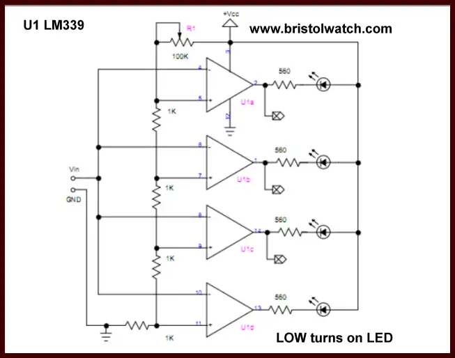
LM339 based 4-bit voltage indicator - click picture for full size.
Above we are using all four comparators in the LM339 as a 4-bit voltmeter. The voltage divider resistors and the 100K pot set the trip on voltages.
Comparator Basics
Also see Voltage Comparator Circuits
A comparator is often an operational amplifier without feedback between the inputs and output. It's either all the way ON (near Vcc) or OFF (near 0 volts). Illustrated in Fig. 2 is a comparator built from a common LM741 op amp.
In this test circuit we use a 12-volt bipolar power supply. In the NEG input on pin 2 is fixed at 6-volts with a Zener diode connected to the + side of the power supply. We will call this Vref.
On the POS input on pin 3 we connect a potentiometer back to + and GND. This is Vin. If Vin is less than 6-volts the output on pin 7 of the LM741 will be about minus 10-volts. Here we use a 1N4001 diode to protect the LED from excessive reverse voltage.
If we adjust the 10K pot to where Vin is greater than Vref the output on pin 7 goes to about plus 10-volts forward biasing the 1N4001 and turning on the LED.
The disadvantage of using the LM741 is the use of a bipolar power supply.
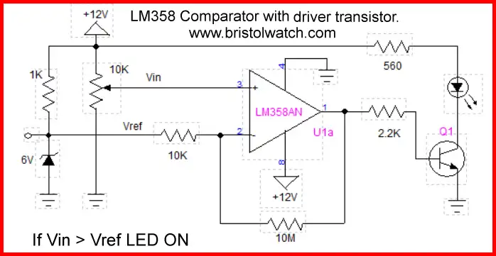
Fig. 2 LM358 based comparator uses
single supply- click picture for full size.
The comparator circuit in Fig. 2 uses a LM358 op-amp instead of the LM741. The LM358 is designed for single supply operation. It does the same thing as Fig. 2 with the addition of Q1 to act as an open collector output driver.
When Vin is less than Vref the output on pin goes to about 10-volts turning on transistor Q1 which turns on the LED. By setting a trip point with the 10K pot one can make an under-voltage indicator.
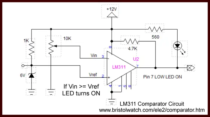
Fig. 3 LM311 based comparator has
an open collector output - click picture for full size.
As a rule for comparator inputs with open collector outputs such as the LM339 or LM311 (not the LM358 circuit):
Current WILL flow through the open collector when the voltage at the MINUS input is higher than the voltage at the PLUS input.
Current WILL NOT flow through the open collector when the voltage at the MINUS input is lower than the voltage at the PLUS input.
Fig. 4 uses a LM311 comparator specifically designed to be ONLY a comparator - all the external parts in Fig. 3 minus the LED circuit, pot, Zener. Its feedback and input resistors are internal. It operates identical to the LM358 circuit.
The external 4.7K resistor is used for interfacing to digital logic by producing a HIGH or 12-volts out when the LM311 is turned off. This is how digital circuits "communicate" with resistive sensors. Setting Vref to a known point and checking the output tell us when Vin is greater than Vref.
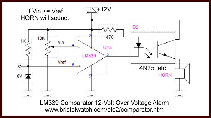
Fig. 4 LM339 comparator over voltage alarm
using opto-coupler to sound horn - click picture for full size.
In Fig. 5 we are using a one of four LM339 quad comparators to sound a horn if Vin goes too high due to Vcc going over 12-volts. The LM339 is equal to 4 LM311s in a single package with common power and GRD connections for all 4 comparators. See Fig. 1 above.
This circuit is useful in say an automobile charging system regulator that fails dumping excessive voltage into system ruining the battery and electronics. Here I used a 4N25 opto-coupler to drive a low power buzzer or horn - the current capacity of the comparator output is low while the opto-coupler is much higher.
See LM339 spec sheet.
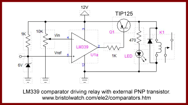
Fig. 5 LM339 comparator driving relay with
external PNP transistor - click picture for full size.
In Fig. 6 we use an external PNP bipolar transistor to drive a relay. When the open collector output of the comparator is turned on current flows through the 1K resistor and the base-emitter junction turning on the transistor completing the circuit for relay K1 and the LED on indicator.
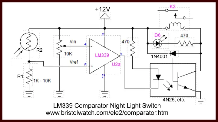
Fig. 6 LM339 comparator uses CdS photocell
to control night light - click picture for full size.
Now we use a LM339 to construct a "night light". The Zener diode has been replaced by a CdS photocell that decreases in resistance in proportion to increasing light levels. As the resistance of R2 decreases in daylight Vref is higher than Vin thus the comparator id off.
As light levels drop R2 increases resistance with Vref falling below Vin turning on a relay though an opto-coupler to turn on lights or whatever. The very same PNP circuit in Fig. 6 would also work. Use the 10K pot to set the trip-on point.
As a final note R1 and R2 can be reversed for the opposite effect. Say turn off a blower motor in a green house as the sun goes down. The photocell could be replaced by a thermistor for temperature.
- Comparator Circuits:
- Comparator Theory Circuits Tutorial
- Comparator Hysteresis and Schmitt Triggers
- Voltage Comparator Information And Circuits
- Looking at Window Comparator Circuits
- Analog Battery Charger Uses Comparators
- YouTube:
- Comparator Circuits Introduction
- Quick navigation of this website:
- Basic Electronics Learning and Projects
- Basic Solid State Component Projects
- Arduino Microcontroller Projects
- Raspberry Pi Electronics, Programming
- Comparator Theory Circuits Tutorial
- Zero-Crossing Detectors Circuits and Applications
- Improved AC Zero Crossing Detectors for Arduino
- Photodiode Circuits Operation and Uses
- Photodiode Op-Amp Circuits Tutorial
- Issues on Connecting MOSFETs in Parallel
- MOSFET DC Relays Using Photovoltaic drivers
- Optocoupler Input Circuits for PLC
- All NPN Transistor H-Bridge Motor Control
- Photo Voltaic Tutorial MOSFET Output Solid State Relays
- Optical Isolation of H-Bridge Motor Controls
- Design 10-Amp 2N3055 Based Power Switch
- TA8050P H-Bridge Motor Control
- Connecting Crydom MOSFET Solid State Relays
- H11L1, 6N137A, FED8183, TLP2662 Digital Output Optocouplers
- Arduino
- Arduino PWM to Analog Conversion
- Arduino Analog Digital Conversion Voltmeter
- Better Arduino Rotary Encoder Sensor
- Simple 3-Wire MAX6675 Thermocouple ADC Arduino Interface
- Hall Effect Magnetic Switches and Sensors
- Transistor-Zener Diode Regulator Circuits
- Build an Adjustable 0-34 volt power supply with the LM317
- Coils for Highly Selective Crystal Radio
- Neon (NE-2) Circuits You Can Build
- Understanding Xenon Flashtubes and Circuits
- LM2575 Simple Switching Voltage Regulators
- Simple 2 Transistor LED Flasher Circuit
- Generating High Voltage with an Inductor
Web site Copyright Lewis Loflin, All rights reserved.
If using this material on another site, please provide a link back to my site.