Fig. 1 click for full size photo.
Better Arduino Rotary Encoder Circuit
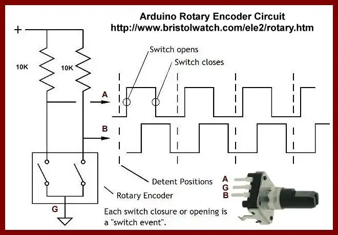
Rotary encoders are often three-wire devices where the phase relationship between the two outputs is an indication of the direction of shaft rotation. This can be a manual control or a disk on a motor shaft.
Shown above is the waveform relationship on channel A and B outputs. If we use the positive going edge of waveform A as a reference, we need to read the logic level channel B.
For example if B is a logical HIGH then we know the direction is say clockwise. And if a logical LOW then we know the direction is counter-clockwise.
The circuit as is suffers from contact noise from the switches and if connected to Arduino or PIC the direction of rotation has to be decided in software which can slow down program response. See the following two examples.
- HEDS-9000 Rotary Encoder Using Arduino Interrupts
- PIC16F628A Using Rotary Encoder to Operate Stepper Motor
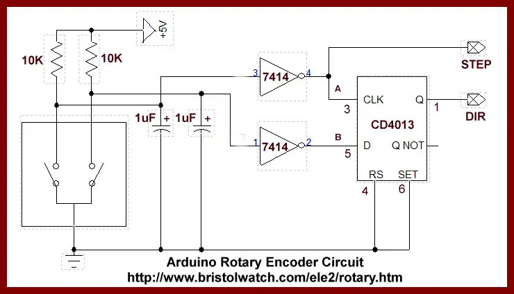
Fig. 2 click for full size photo.
In the above circuit we use a 1uF capacitor with a SN7414 Schmitt trigger input NAND gates that clean up the switch contact noise.
We use a CD4013 D Flip-Flop that operates as follows: If B is HIGH on pin 5 when A goes from LOW to HIGH on pin 3 the Q output on pin 1 goes HIGH and is stored there. By reading that single bit we know direction say CW.
If the shaft is rotated in the opposite direction B is a LOW on pin 5 is stored on Q when A on pin 3 goes LOW to HIGH. Now we know the shaft was turned in the opposite direction (CCW) when Q is polled by a micro-controller.
In addition Arduino or PIC can poll STEP as a count pulse in addition change in direction on DIR.
Arduino Code with LCD Display
The CLK pulse is connected to DP2 and utilizes interrupt 0 with ISR read_rotary which checks the state of DIR on DP3 and increments or decrements the variable counter which is displayed on the LCD display.
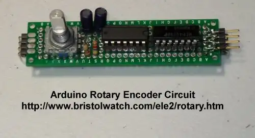
Actual Circuit on PC board.
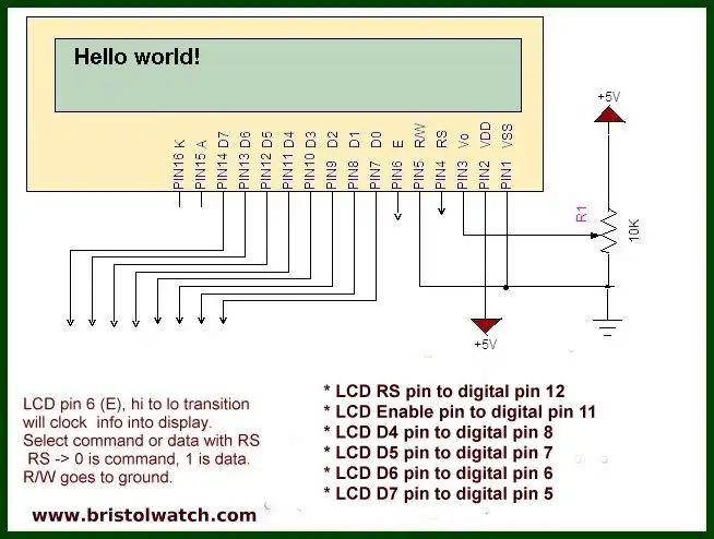
Demonstrates the use a 16x2 LCD display. The LiquidCrystal library works with all LCD displays that are compatible with the Hitachi HD44780 driver.
 The circuit:
 * LCD RS pin to digital pin 12
 * LCD Enable pin to digital pin 11
 * LCD D4 pin to digital pin 8
 * LCD D5 pin to digital pin 7
 * LCD D6 pin to digital pin 6
 * LCD D7 pin to digital pin 5
 * LCD R/W pin to ground
 * 10K resistor:
 * ends to +5V and ground
 * wiper to LCD VO pin (pin 3)
See LCD Connections.
// include the library code:
#include <LiquidCrystal.h>

#define STEP 2 //  interrupt 0
#define DIR 3

static int counter = 0;
char myString[19];

// initialize the LCD library with
// the numbers of the interface pins
LiquidCrystal lcd(12, 11, 8, 7, 6, 5);

void setup() {
  // set up the LCD's number of columns and rows:
  lcd.begin(16, 2);
  pinMode(STEP, INPUT);
  pinMode(DIR, INPUT);
  attachInterrupt(0, read_rotary, FALLING);
  lcd.print("Count = ");
}

void loop() {
  lcd.setCursor(8, 0); // row 0 col 9
  lcd.print(counter);
  lcd.print("    ");
  delayMicroseconds(10000);
}

// read bit on DIR on D3
void read_rotary(void)   {
  if (digitalRead(DIR)) counter--;
    else counter++;
}
- Quick navigation of this website:
- Basic Electronics Learning and Projects
- Basic Solid State Component Projects
- Arduino Microcontroller Projects
- Raspberry Pi Electronics, Programming
- Comparator Theory Circuits Tutorial
- Zero-Crossing Detectors Circuits and Applications
- Improved AC Zero Crossing Detectors for Arduino
- Photodiode Circuits Operation and Uses
- Photodiode Op-Amp Circuits Tutorial
- Issues on Connecting MOSFETs in Parallel
- MOSFET DC Relays Using Photovoltaic drivers
- Optocoupler Input Circuits for PLC
- All NPN Transistor H-Bridge Motor Control
- Photo Voltaic Tutorial MOSFET Output Solid State Relays
- Optical Isolation of H-Bridge Motor Controls
- Design 10-Amp 2N3055 Based Power Switch
- TA8050P H-Bridge Motor Control
- Connecting Crydom MOSFET Solid State Relays
- H11L1, 6N137A, FED8183, TLP2662 Digital Output Optocouplers
- Arduino
- Arduino PWM to Analog Conversion
- Arduino Analog Digital Conversion Voltmeter
- Better Arduino Rotary Encoder Sensor
- Simple 3-Wire MAX6675 Thermocouple ADC Arduino Interface
- Hall Effect Magnetic Switches and Sensors
- Transistor-Zener Diode Regulator Circuits
- Build an Adjustable 0-34 volt power supply with the LM317
- Coils for Highly Selective Crystal Radio
- Neon (NE-2) Circuits You Can Build
- Understanding Xenon Flashtubes and Circuits
- LM2575 Simple Switching Voltage Regulators
- Simple 2 Transistor LED Flasher Circuit
- Generating High Voltage with an Inductor
Web site Copyright Lewis Loflin, All rights reserved.
If using this material on another site, please provide a link back to my site.